Published on May 5, 2024
Wireless Boiler Switch
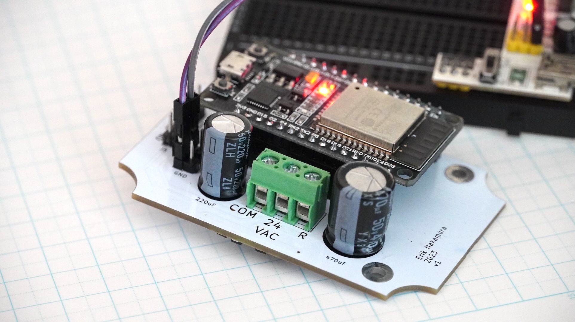
To replace a broken thermostat I designed and built a WiFi enabled switch powered by the boiler controller's native 24 VAC line.
Project Goals
My goal was to create a wifi-controlled switch so that I could turn the heating on and off through my phone. I also wanted to power the device using the available 24 VAC to avoid the need for batteries or external power supplies.
How The Boiler Works
The boiler is piloted by a control board comprised mainly of solenoid relay switches. These relays activate the various pumps and the boiler itself to supply heat around the house as needed.
Several pairs of terminals on the control board allow the relays to be externally controlled by a thermostat or other switch. A terminal pair is comprised of a 24 VAC output and an input. By connecting and disconnecting the output and input of a terminal pair, the solenoid is energized to close the switch and power the equipment.
Unlike a digital logic-level signal that merely indicates an on/off state, the boiler controller operates by accepting driving signals which directly power the solenoid switches. The job of the control board, then, is only to produce the driving signal (with a step-down transformer), and split incoming drive signals to the necessary solenoids. For example, when a pump's switch is activated by an incoming drive signal, the board needs to route that signal so it also activates the boiler's main power switch.
This system is a domino cascade of electrical switches. A small switch (thermostat) controls a 24 VAC drive signal, which in turn powers another switch (control board relay) that controls 120 VAC drive power to the appliances. In this manner, a low voltage logic level signal can be used to control high voltage power.
In addition to the drive signal the board also provides a 24 VAC auxiliary power line to supply energy to external thermostats and switches.
I don't quite understand why the thermostat can't power itself directly off of the drive signal. I think this should be technically possible but it might be avoided by convention. If thermostats could power themselves from the drive signal, they would only need two wires back to the boiler controller instead of three.
Implementation
Schematic
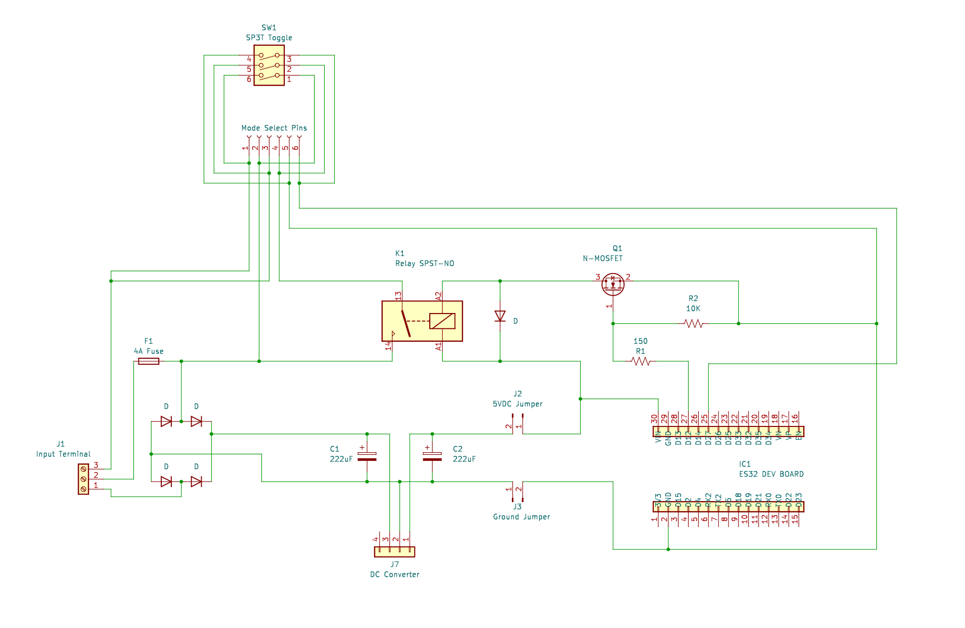
I ended up omitting the fuse because the boiler control board already has one.
PCB
I designed the PCB in KiCAD. I had to make custom footprints for the ESP32 dev board and the Omron relay.
The relay I chose is the Omron G6L-1P DC5. They advertized it as "One of the the Thinnest Relays in the World" on the data-sheet so I had to try it. These relays are indeed very small and thin, which allowed me to fit one underneath the ESP32 dev board, making the overall layout much more compact. The only downside of these small relays is that they are less common and therefor more difficult to replace. The relay is probably the first part of this board that would fail, since its the only moving part.
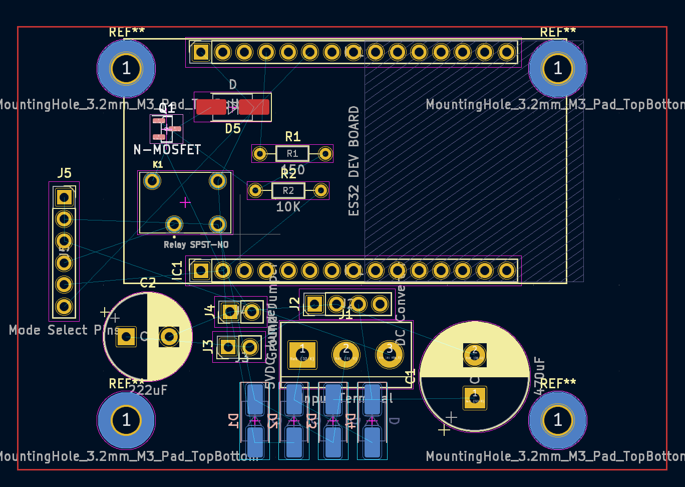
I opted to use an off-the-shelf DC-DC buck converter to produce the 5V DC needed to power the ESP32 and drive the relay. Switch mode converters (especially compact ones), operate at high frequencies, thus making their implementation a bit more tricky than something I could DIY. This high frequency operation also sloshes around a lot of electrons which produces electromagnetic noise. To shield the antenna on the ESP32, I situated the converter at the bottom of the PCB, and filled both PCB layers with copper ground planes.
Note the flyback arrestor diode between the terminals of the relay solenoid. Most common relay breakout boards I've seen will use a schottky diode here, which is technically preferred due to the lower forward voltage drop and faster clamping (recovery) time. However, in this application with very slow switching frequencies, I opted to use the same diode across the whole design to minimize the BOM.
It's not pictured in the screenshot, but I also added a router-cut edge to the board so it would fit inside the enclosure.
I sent the gerbers overseas for fabrication. The cost was $2 for 5 board plus about $20 shipping. What a treat!
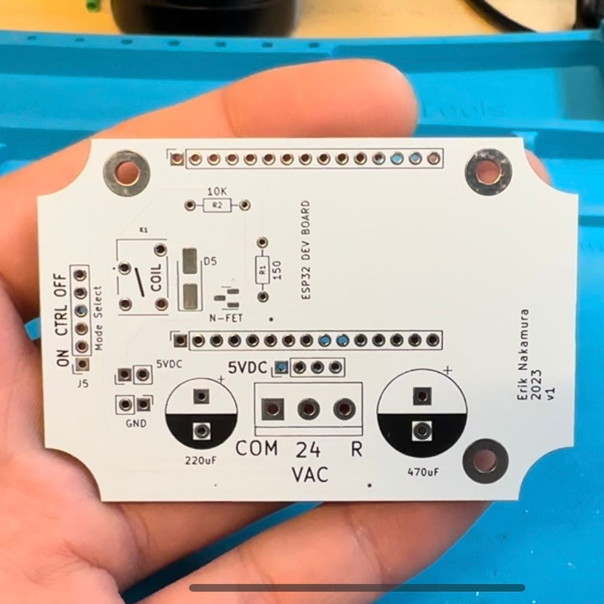 front of PCB | back of PCB |
|---|
Bill of Materials
I splurged on the premium oversized components to compensate for my lack of electronics design skills.
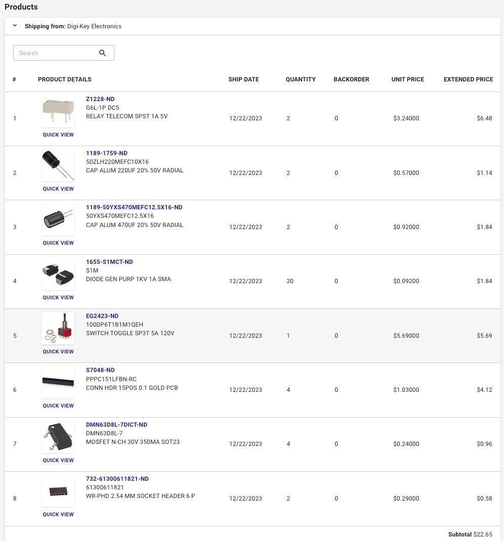
I also used the aforementioned converter from Pololu, a small ABS project enclosure, a cable gland, and a 3 conductor cable.
I think the total cost was less than $100.
Assembly
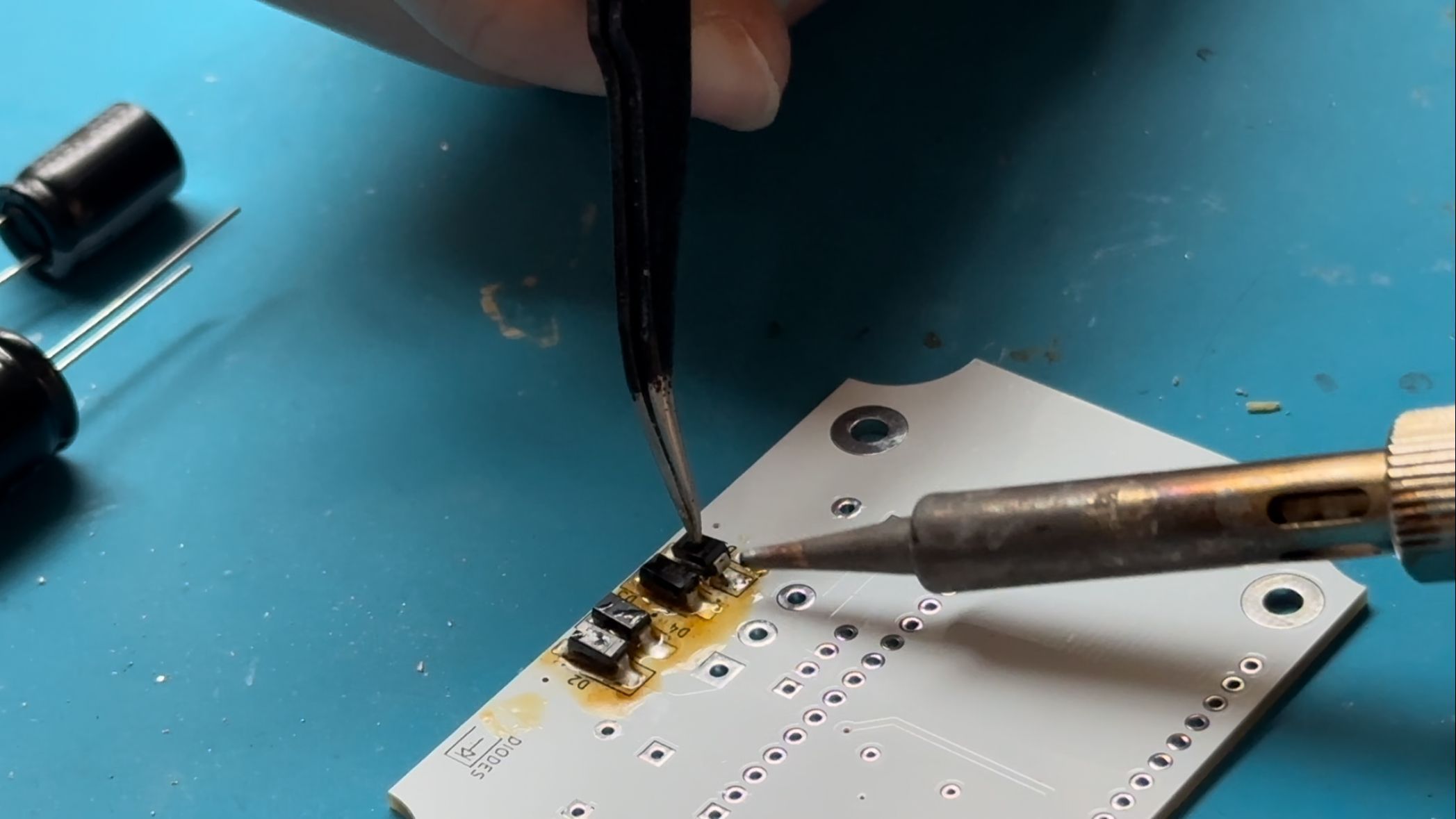
Assembly was straight forward. I don't do much surface mount soldering so this was good practice. I learned that with large SMD parts like the diodes, it better to solder down one side at a time.
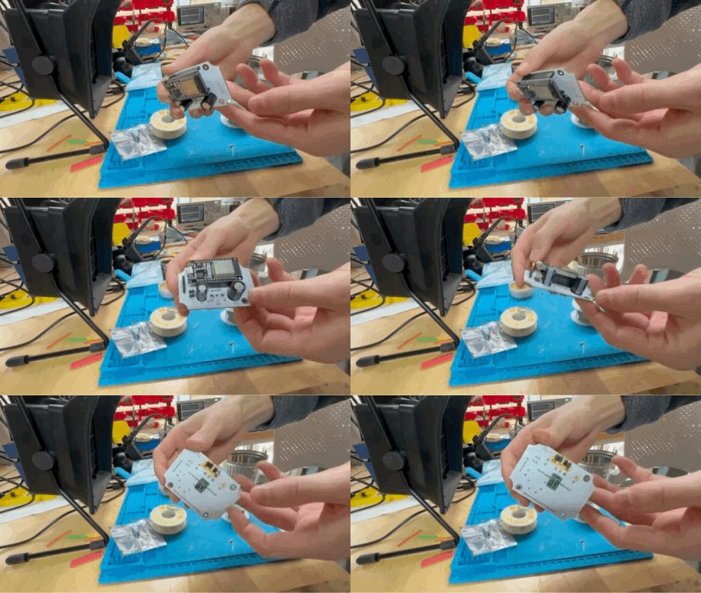
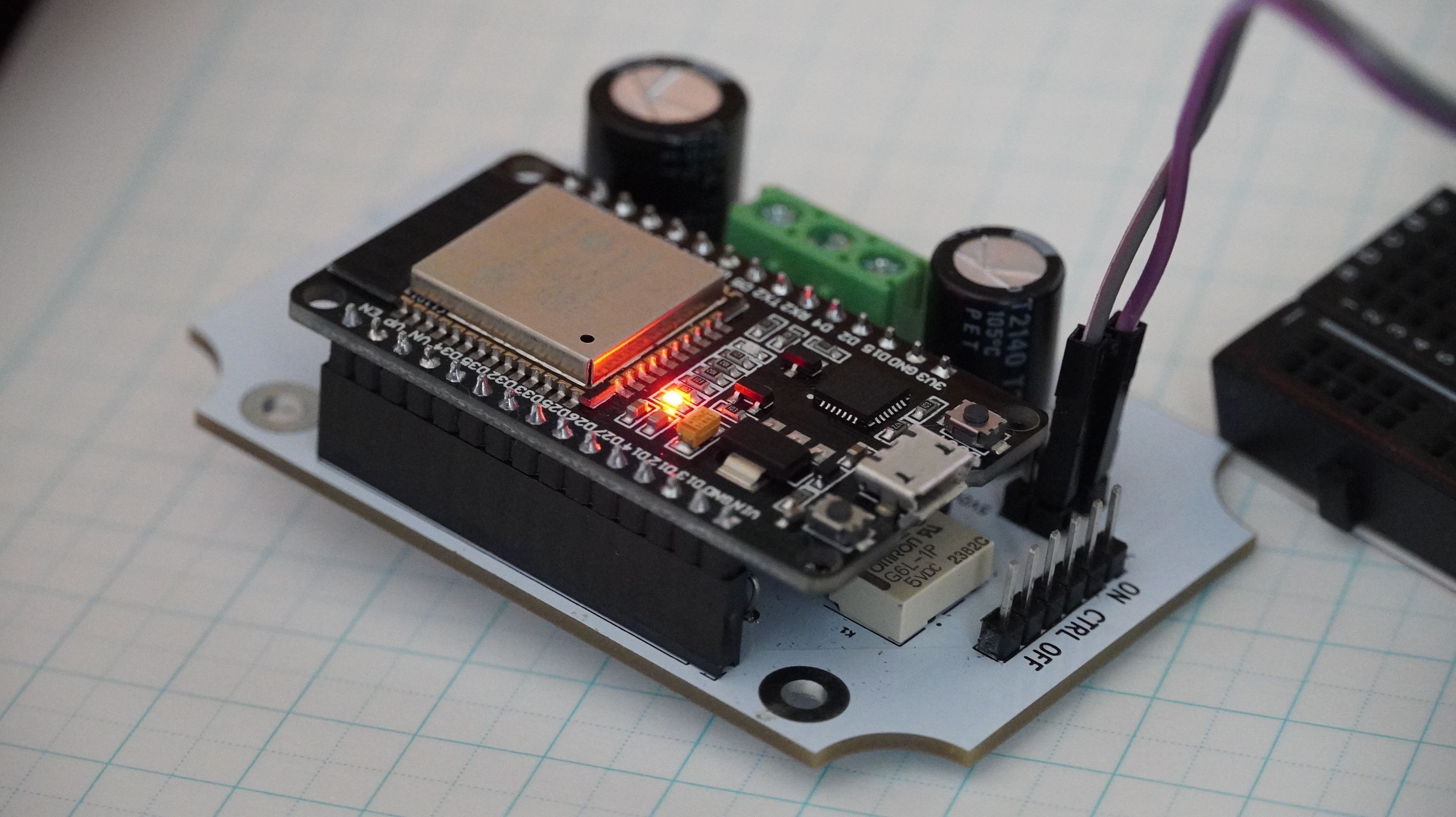
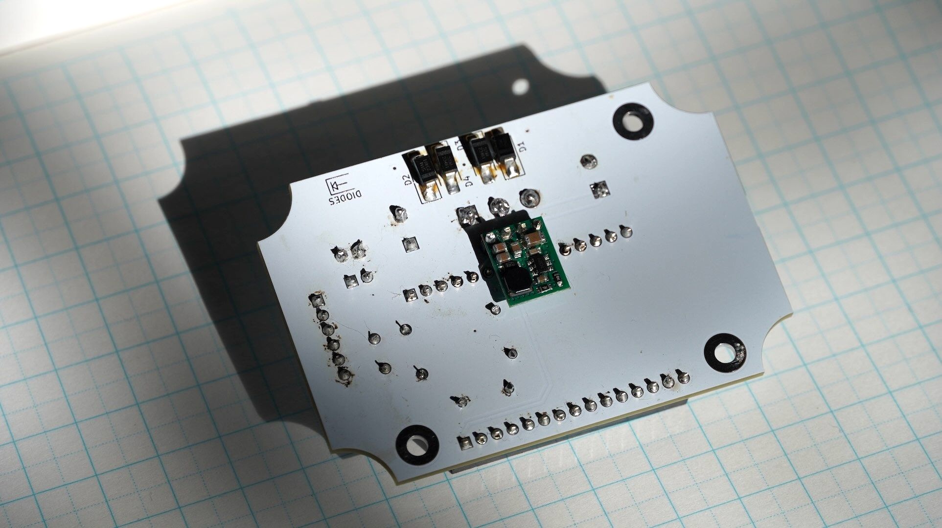
They're not pretty but the solder joints work.
Programming
I opted to use Blynk to make the ESP32 controllable from my iPhone.
I found myself quickly hitting their limit of 5 "data streams" for the free tier. To work around this, I found that I could encode much longer messages in text versus using separate number or boolean value data streams.
From a user-interface standpoint, text is great because it communicates a clear message. The Blynk app I created is also used by other people in the house, so it needed to be easily understandable. Instead of using confusing symbols or colors to indicate a state, it simply prints a message that explains it.
The full ESP32 firmware can be found at the end of this post and is available under the MIT license.
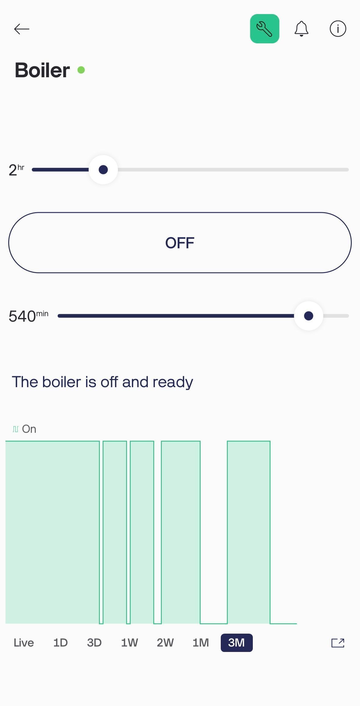 use sliders to set the on-time in hours and a delay in minutes | 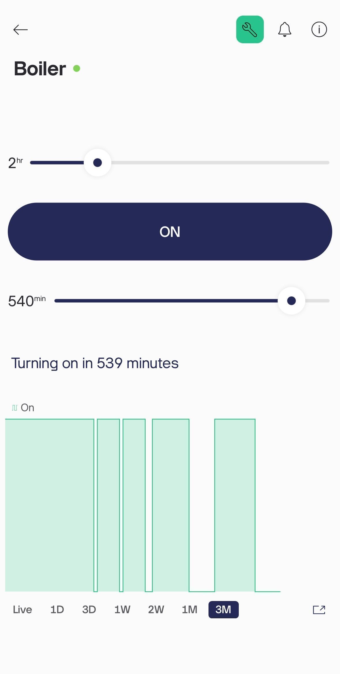 feedback is provided when the delay timer is started | 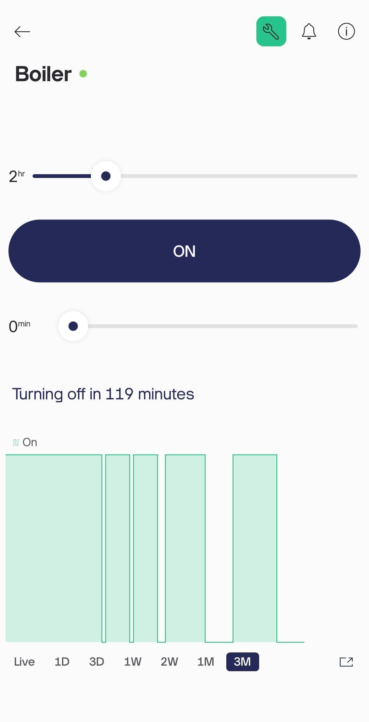 when active, the remaining on-time is shown |
|---|
I thought the chart could be a cool feature but it doesn't work well for long time-frames with binary on-off data.
Installation
I wired the boiler to the control panel just like any commercially available smart thermometer. I nailed it to the wall near the boiler where it would get a good wifi signal.
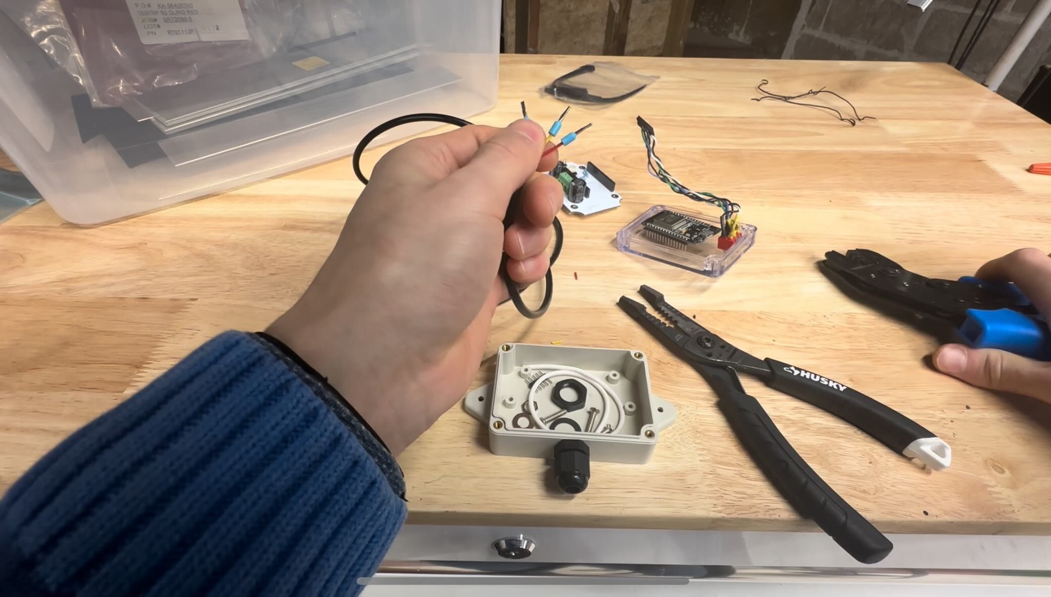
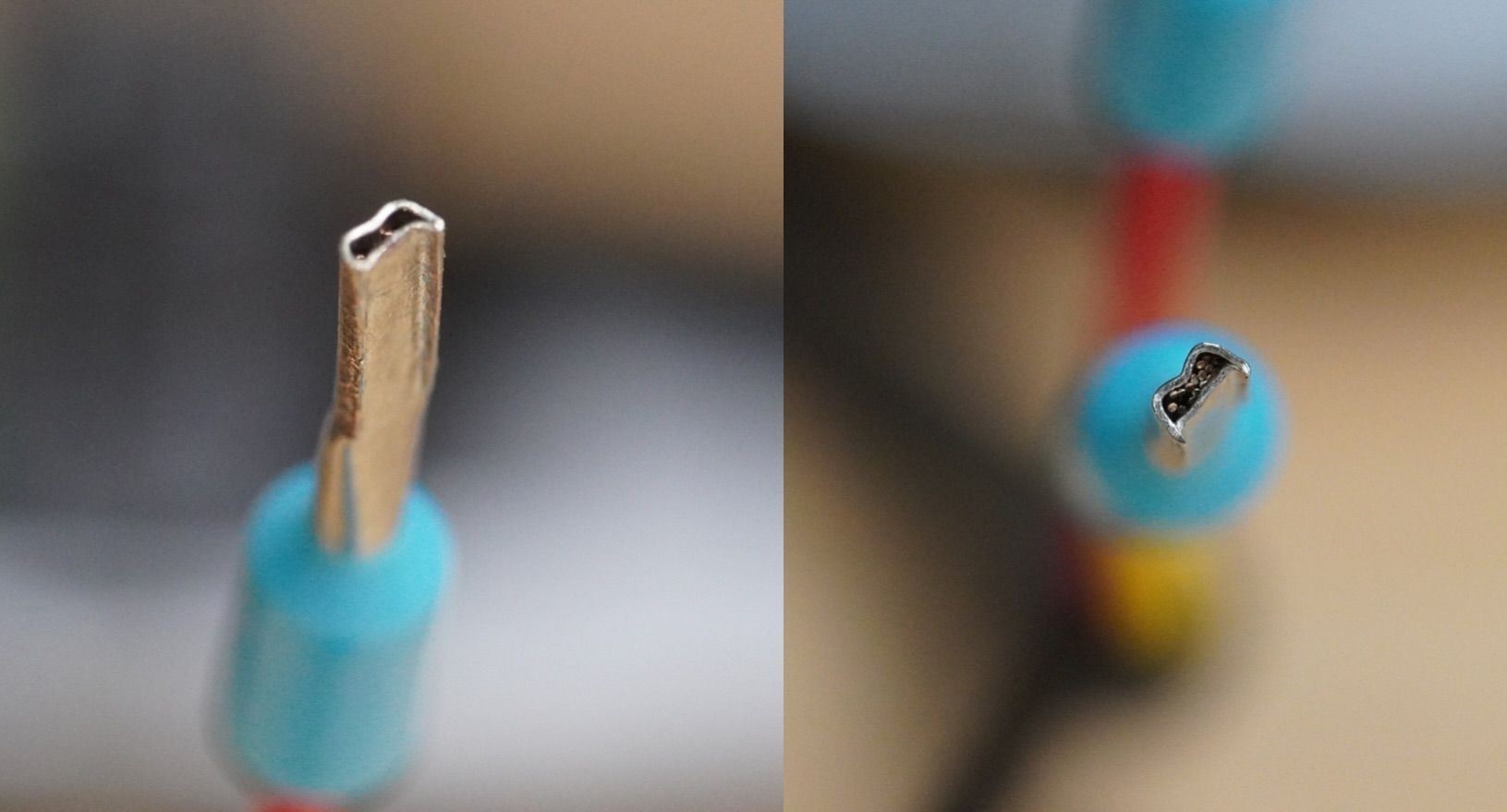
I used ferules on all screw terminal connections.
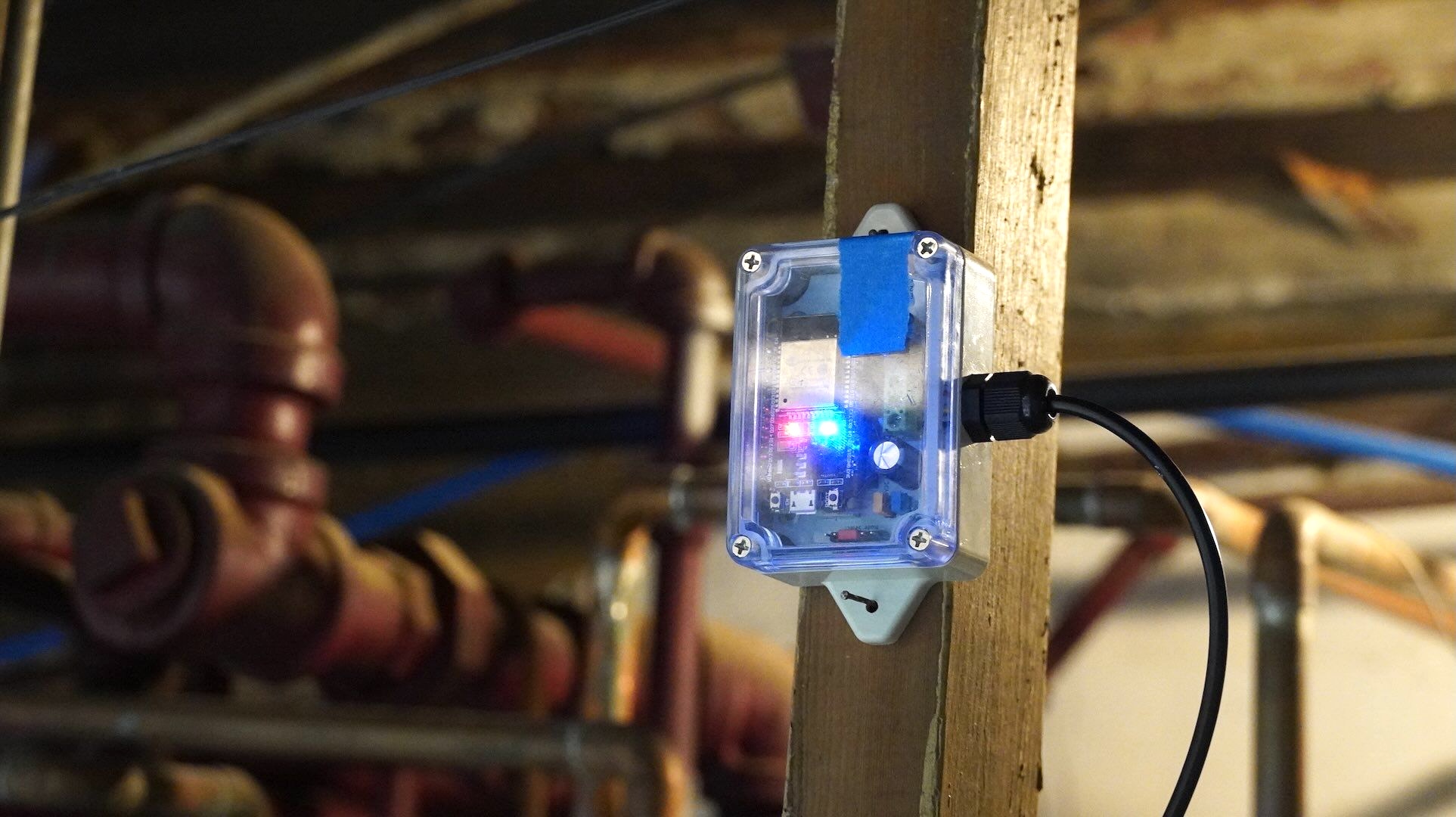
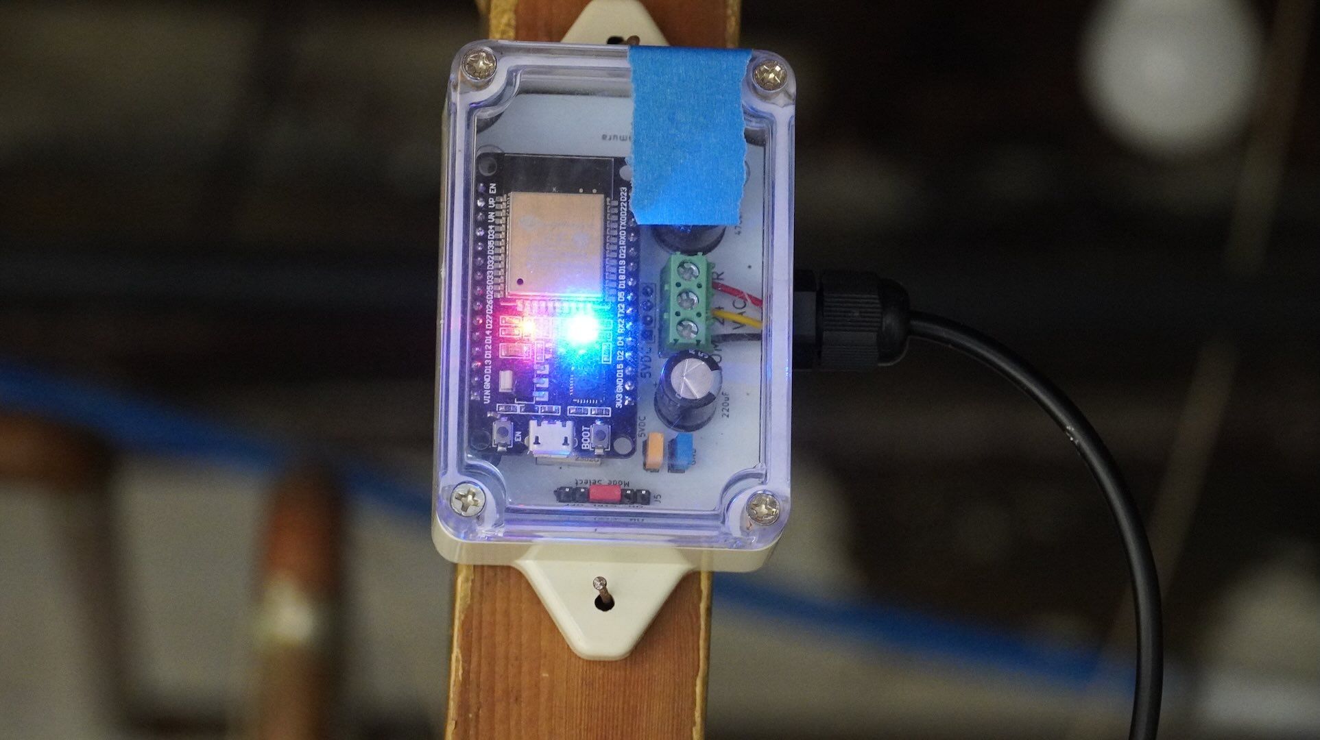
The blue tape is covering up the hole for the toggle switch so dust doesn't get in the enclosure. I had to remove the switch because it didn't work the way I thought it would (see Blunders below).
Usage and Next Steps
My tolerance to cold became very high this winter which is, unfortunately, inversely proportional to the effectiveness of this system. Since there is no thermometer built in to the system, the human user is the thermometer. It wasn't until I already felt uncomfortably cold that I would remember to turn on the boiler, which would take at least an hour to warm up the radiators and iron pipes.
It was nice to turn it on before bed with a 5-6 hour delay so I could wake up to warm radiators. Still, a thermostat is necessary for hands-free comfort.
I'm also planning to download the on-off data and correlate it to the monthly heating bill to produce a cost per hour heating rate. My estimate is in the range of $5-10 per hour. This high cost is why I thought a manually controlled system would be beneficial.
Blunders
I realized that the toggle switch I purchased does not work like I thought it would. I naively assumed that a single throw triple pole (SP3T) switch would be like 3 switches in one where each switch is activated one-at-a-time. This is not how the toggle switch works. In fact, I couldn't find any toggle switch with a simple terminal configuration like that. Instead, some terminals are interconnected and different pairs are both opened and closed depending on the switch state. I couldn't figure out how to easily map this to the series of switches that my circuit expects, so I covered over the hole in the enclosure with some masking tape and jumper'd the ON state as a temporary permanent solution.
/*
Copyright 2024 enroot2.com

Permission is hereby granted, free of charge, to any person obtaining a copy of this software and associated documentation files (the “Software”), to deal in the Software without restriction, including without limitation the rights to use, copy, modify, merge, publish, distribute, sublicense, and/or sell copies of the Software, and to permit persons to whom the Software is furnished to do so, subject to the following conditions:

The above copyright notice and this permission notice shall be included in all copies or substantial portions of the Software.

THE SOFTWARE IS PROVIDED “AS IS”, WITHOUT WARRANTY OF ANY KIND, EXPRESS OR IMPLIED, INCLUDING BUT NOT LIMITED TO THE WARRANTIES OF MERCHANTABILITY, FITNESS FOR A PARTICULAR PURPOSE AND NONINFRINGEMENT. IN NO EVENT SHALL THE AUTHORS OR COPYRIGHT HOLDERS BE LIABLE FOR ANY CLAIM, DAMAGES OR OTHER LIABILITY, WHETHER IN AN ACTION OF CONTRACT, TORT OR OTHERWISE, ARISING FROM, OUT OF OR IN CONNECTION WITH THE SOFTWARE OR THE USE OR OTHER DEALINGS IN THE SOFTWARE.
*/

#define BLYNK_TEMPLATE_ID "template_id"
#define BLYNK_TEMPLATE_NAME "boiler control"
#define BLYNK_AUTH_TOKEN "doritos_nachos_preparados"

/* Comment this out to disable prints and save space */
#define BLYNK_PRINT Serial

#include <WiFi.h>
#include <WiFiClient.h>
#include <BlynkSimpleEsp32_SSL.h>

BlynkTimer timer;

// Your WiFi credentials.
// Set password to "" for open networks.
char ssid[] = "";
char pass[] = "";

const int onboardLedPin = 2;
const int mosfetPin = 27;
const int offSensePin = 12;

bool isBoilerOn = false;
bool isForcedOff = false;

// All times are in seconds
unsigned long onTimeRemaining = 0;
unsigned long delayTimeRemaining = 0;

unsigned long userSetOnTime = 0;
unsigned long userSetDelayTime = 0;

int onTimerId = -1;

// This tally is used to only send updates every 5 seconds
int onStateWaitTally = 5;

// There are 5 "data streams"
// V0 "On time" the amount of time to keep the boiler on in hours
// V1 "Delay time" the amount of time to delay turning on in minutes
// V2 "Switch" activate or deactivate the boiler
// V3 "State message" a short message about the current state
// V4 "On state" 1 if the boiler is on, 0 if off, -1 if forced off

void updateStateMessage()
{
  if (delayTimeRemaining > 0)
  {
    // Convert seconds to minutes for delay time
    long delayMinutes = delayTimeRemaining / 60;
    // For development
    //delayMinutes = delayTimeRemaining; // DEVONLY
    // Create the string with the actual delay time
    String message = "Turning on in " + String(delayMinutes) + " minutes";
    Blynk.virtualWrite(V3, message);
  }
  else
  {
    // Convert seconds to minutes for on time
    long onTimeMinutes = onTimeRemaining / 60;
    // For development
    //onTimeMinutes = onTimeRemaining; // DEVONLY
    // Create the string with the actual on time
    String message = "Turning off in " + String(onTimeMinutes) + " minutes";
    Blynk.virtualWrite(V3, message);
  }
}

void turnBoilerOff(bool isLocal)
{
  timer.deleteTimer(onTimerId);
  digitalWrite(mosfetPin, LOW);
  digitalWrite(onboardLedPin, LOW);
  Blynk.virtualWrite(V3, "The boiler is off and ready");
  Blynk.virtualWrite(V4, 0);
  // Don't write back to Blynk if the off signal came from Blynk
  if (isLocal)
  {
    Blynk.virtualWrite(2, 0);
  }
  isBoilerOn = false;
}

void turnBoilerOn()
{
  digitalWrite(mosfetPin, HIGH);
  digitalWrite(onboardLedPin, HIGH);
  Blynk.virtualWrite(V4, 1);
  isBoilerOn = true;
  // We keep the timer alive
}

void updateOnState()
{
  bool shouldDelayMessageUpdate = true;
  if (isBoilerOn)
  {
    // Check if we should shut the boiler off
    if (onTimeRemaining > 0)
    {
      onTimeRemaining--;
    }
    else
    {
      // Turn the boiler off
      turnBoilerOff(true);
      // We don't want to update the state message
      // turnBoilerOff will update it
      return;
    }
  }
  else
  {
    if (onTimeRemaining > 0 && delayTimeRemaining > 0)
    {
      delayTimeRemaining--;
    }
    else if (onTimeRemaining > 0)
    {
      turnBoilerOn();
      shouldDelayMessageUpdate = false;
    }
  }
  if (shouldDelayMessageUpdate)
  {
    // Don't write to Blynk too much, every 5 seconds is plenty
    // For development this should be set to 1 or 2 instead DEVONLY
    if (onStateWaitTally < 5)
    {
      onStateWaitTally++;
    }
    else
    {
      updateStateMessage();
      onStateWaitTally = 0;
    }
  }
  else
  {
    updateStateMessage();
    onStateWaitTally = 0;
  }
}

void enterOnState()
{
  // C++ is assignment by reference for longs
  onTimeRemaining = userSetOnTime;
  delayTimeRemaining = userSetDelayTime;
  timer.deleteTimer(onTimerId); // Just to be sure
  onTimerId = timer.setInterval(1000L, updateOnState);
  onStateWaitTally = 5;
  updateOnState();
  Serial.println("Entering on state");
  Serial.print("On time remaining: ");
  Serial.print(onTimeRemaining);
  Serial.print(" delayTimeRemaining ");
  Serial.println(delayTimeRemaining);
}

// This function is called when the on time slider value is changed in Blynk
BLYNK_WRITE(V0)
{ // On Time in hours
  float onTimeHours = param.asInt();
  userSetOnTime = onTimeHours * 3600; // Convert hours to seconds
  // For testing
  //userSetOnTime = onTimeHours; // DEVONLY
}

// This function is called when the delay time slider value is changed in Blynk
BLYNK_WRITE(V1)
{ // Delay Time in minutes
  float delayTimeMinutes = param.asInt();
  userSetDelayTime = delayTimeMinutes * 60; // Convert minutes to seconds
  // For testing
  // userSetDelayTime = delayTimeMinutes; // DEVONLY
}

// This function is called when the switch in Blynk is toggled
BLYNK_WRITE(V2)
{
  int switchState = param.asInt();
  if (switchState == 1)
  { // Switched On
    enterOnState();
  }
  else
  {
    turnBoilerOff(false);
  }
}

BLYNK_CONNECTED()
{
  Blynk.syncAll();
}

void setup()
{
  Serial.begin(9600);

  pinMode(onboardLedPin, OUTPUT);
  pinMode(mosfetPin, OUTPUT);
  pinMode(offSensePin, INPUT_PULLUP);
  Blynk.begin(BLYNK_AUTH_TOKEN, ssid, pass);
}

void loop()
{
  Blynk.run();
  timer.run(); // Initiates SimpleTimer
  int offSense = digitalRead(offSensePin);
  if (offSense == HIGH)
  {
    // The pin is normally pulled high, so high means not forced off
    if (isForcedOff)
    {
      Blynk.syncAll();
      Serial.println("Not forced off anymore");
    }
    isForcedOff = false;
  }
  else
  {
    if (isForcedOff == false)
    {
      Blynk.virtualWrite(V3, "The boiler is forced off");
      Blynk.virtualWrite(V2, 0);
      Serial.println("Changed to forced off");
    }
    isForcedOff = true;
  }
}
The content of this post, excluding the thumbnail image, is licensed under:
Attribution-NonCommercial-ShareAlike 4.0 International


Use of this content is still subject to the terms described in the license section of the about page.