Published on May 29, 2026
G4 LED Light Bulbs
I designed and built a small LED light bulb to provide a perfect dimming experiencing for a light fixture. I also built a PWM power supply from scratch to power the bulbs.
Backstory
A friend commissioned me to re-wire a lamp with very cool blown glass orbs ornamenting a tall brass floor standing stem. I wired the lamp with 20 AWG stranded copper silicone wire, connecting all bulb sockets in parallel within the tube that forms the stem.
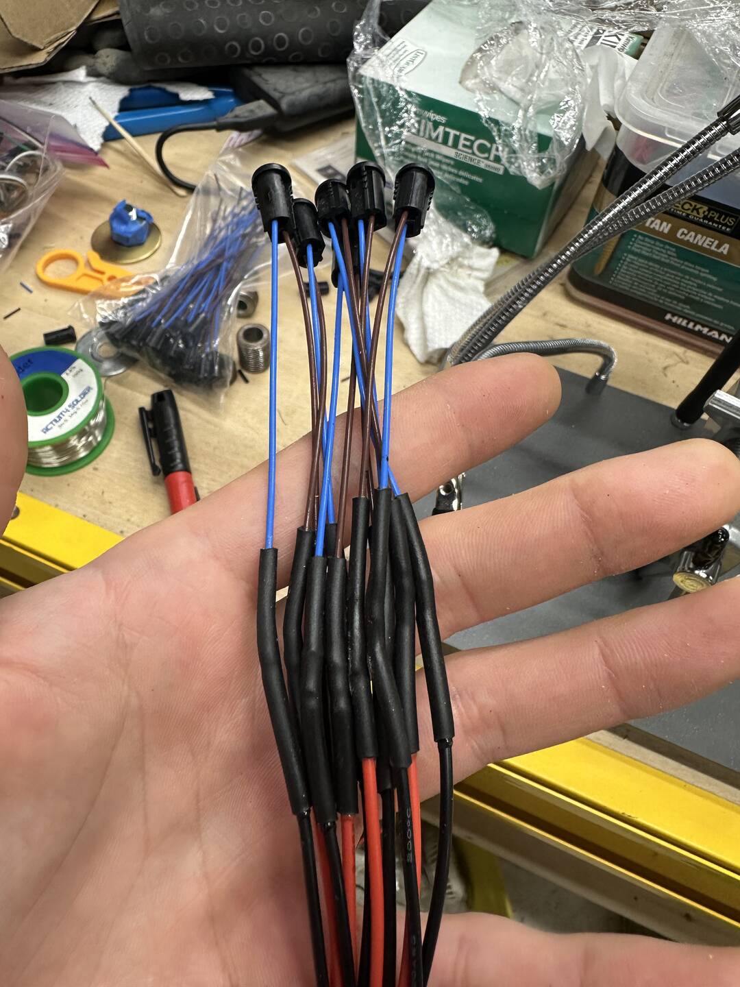
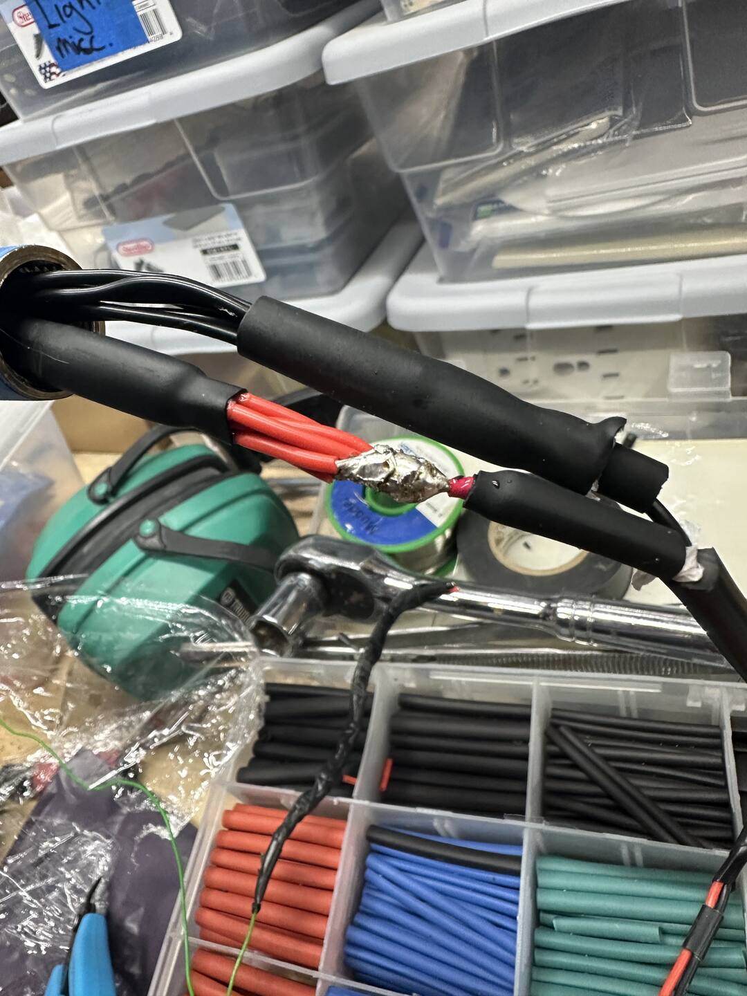
Then I used a jacketed 18 AWG for the portion of cable exiting the lamp with a DC barrel jack for power input.
We threw in the LED bulbs they already had, the lamp lit up, and the real story begins.
Dimming is Critical
One important request from my friend was that the light should be dimmable, smoothly, down to zero. It seemed important to them, and that made me reflect on dim-ability and the role it plays on the quality of indoor lighting.
Subjectively I'm sure, all who see would agree that we are naturally perceptive to and influenced by the brightness of light around us. Modulating the intensity of light in a space adapts it to the occasion, enhancing occupant comfort and generally making spaces more usable and human-centric.
In the same vein of thoughtful design, these dimmable bulbs would also need the right color temperature (warm, in this case) and excellent color rendering index (CRI).
CRI measures how accurately an "artificial" light source (LEDs) renders colors compared to a natural reference illuminant, on a scale from 0–100. A CRI of 100 means perfect color accuracy relative to the reference, but anything 95+ would be a good target for this lamp.
For cool daylight LEDs, the reference illuminant is the sun, and for the warm LEDs we'll be using, the reference is the glow of a red hot filament. Mimicking these natural light sources is important because they feel comfortable and familiar by instinct.
If I Could Buy it, I Would
I did some cursory research but failed to find G4 socket DC bulbs marketed as PWM dimmable. Halogen lights would be easy to dim and perfect CRI by definition, but they run very hot, so using them was out of question for safety reasons.
My searches came up completely empty on PWM dimmable LED bulbs.
I realized that the root cause of the problem is that LED G4 bulbs are designed for maximum compatibility, so they contain circuitry to make them work with both AC and DC power sources.
The AC power source circuitry contains capacitors to smooth out the voltage for the LEDs. The capacitors prevent PWM dimming from working because they buffer the incoming power so that rapidly turning the LEDs off and on is not possible.
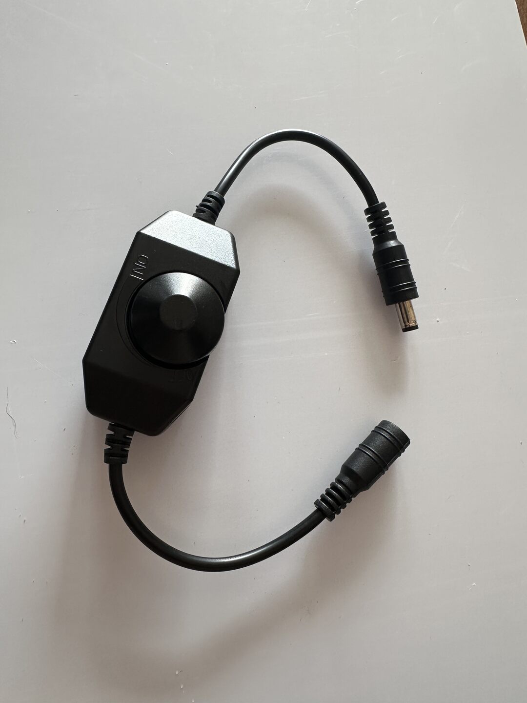
I tried throwing a PWM dimmer on the existing bulbs and it kind of worked, but the lights did not dim down very low before cutting off.
A PWM Optimized LED Circuit
A PWM optimized circuit is one that allows for rapidly turning the LEDs on and off. In practice, this means eliminating components that store energy such as capacitors and inductors.
A simple LED circuit with no energy storing components is one comprising LEDs and resistors in series. The LEDs connected in series allow each to drop its preferred forward voltage, and the resistor(s) handle the remaining voltage while limiting the current.
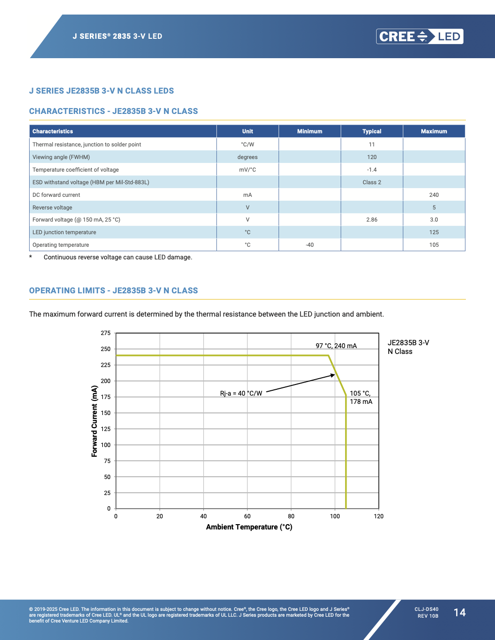
First, I started by researching small LED emitters I could surface mount on a circuit board. I narrowed in on the CREE JE2835 for their warm color temperature (2700K) and high CRI (95). The exact part number can be found in the BOM below.
I wanted to stick with the same 12V power supply currently in use with the lamp. Looking up the voltage drop across the CREE LEDs in their data sheet, I found I could string 3 in series to stay safely within 12 volts.
I fired up KiCad and put together this circuit.
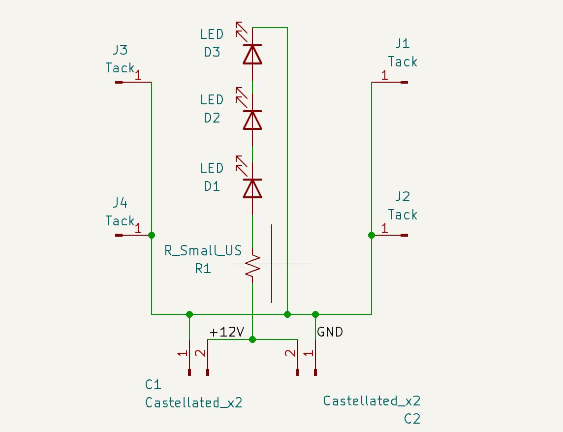
The resistor in the circuit will determine how much current flows through the LEDs.
Each LED typically drops 2.86V according to the datasheet. Because they are in series the total drop across all 3 is:
We will be using a 12V power supply, so the remaining voltage will be dropped across the resistor:
The circuit behaves according to Ohm's law, where the current is proportional to the voltage:
So to identify the resistor value we can choose a target current. The table below shows the resistor values for target currents equal to 25–100% of the LEDs' rated current (150 mA).
| Target (%) | Target Current (mA) | Resistor Value (Ω) |
|---|---|---|
| 25% | 37.5 | 91.2 |
| 50% | 75.0 | 45.6 |
| 75% | 112.5 | 30.4 |
| 100% | 150.0 | 22.8 |
Resistor values are produced in the E series of prefered numbers so I'll search DigiKey for the standard values somewhere around the resistances calculated in the table above. I purchased a range of various resistor values to test.
A Bulb Made of Circuit Boards
My ideas was to connect four rectangular boards along their long edges forming the walls of a tower. The LEDs would be mounted to the outside of each wall, and a square base at the bottom would tie the walls together and provide attachment points for the G4 bulb pins.
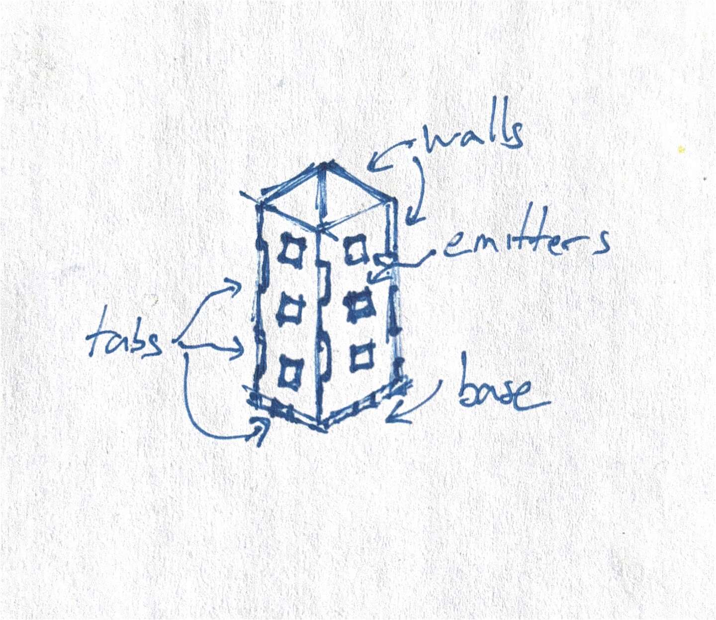
In order to attach the circuit boards to eachother, my first idea was to use castilated pads. My thinking was that castilated pads would allow for both mechanical and electrical connections without the addition of any parts to the BOM.
In addition to castillated pads I intended to use tabs and cutouts to align the boards and strengthen their mechanical connection.
Castillated Pad Layout
The base piece was easy to lay out since it would be a symetrical square with only one real component, the pins.
On a G4 bulb, the pins are placed 4mm center-to-center. Ostensibly, that is where the 4 in G4 comes from.
To creat the castilated pads I first created a custom footprint based on a standard plated through hole with pads, and simply placed the pads so that they would be bisected by the edge cut of the board.
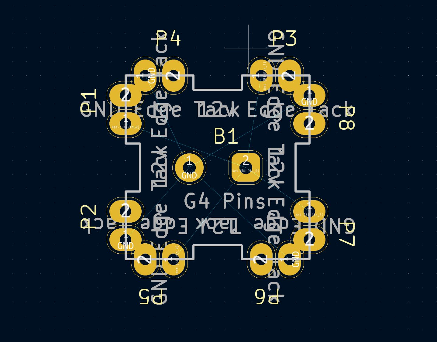
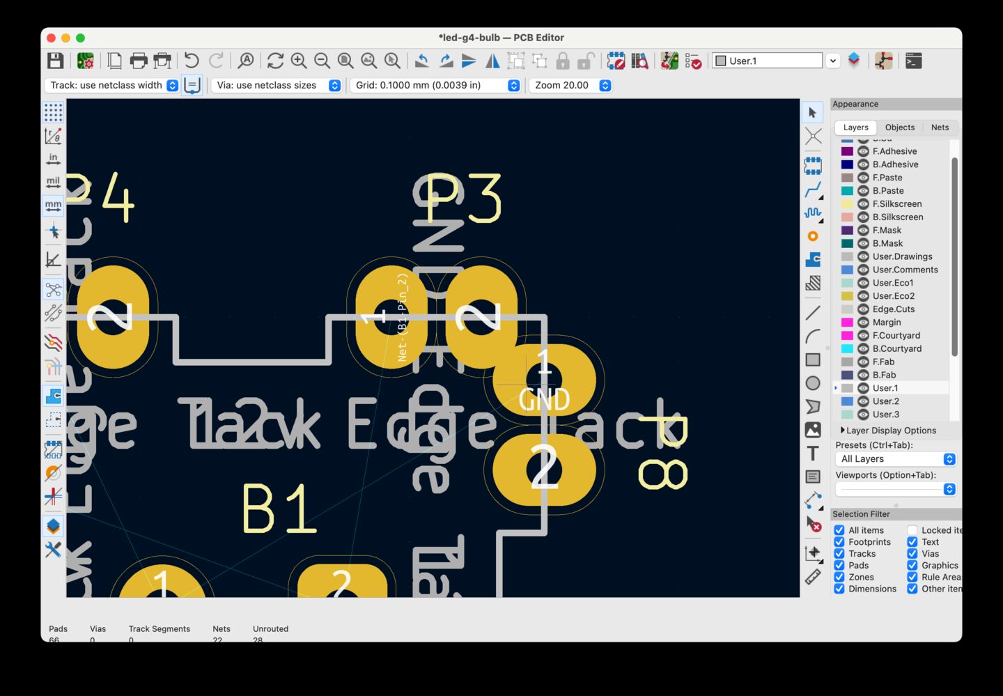
For the side wall boards I used larger castillated pads and tabs.
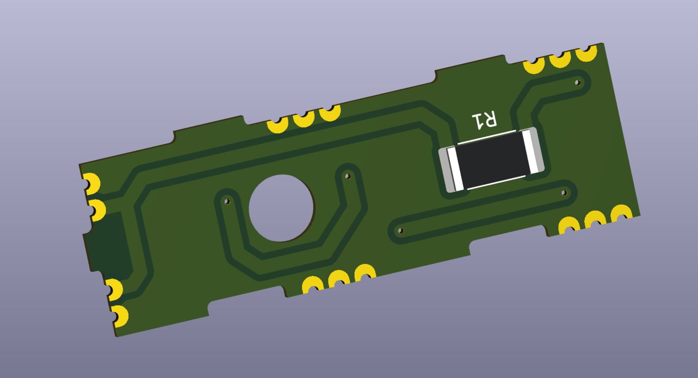
Note the hole in the middle of the board. I added the hole so air could flow into the center of the bulb forming a kind of chimney to improve cooling.
Panelized PCB
The boards that form the bulb are very small, (the base is 14x14mm), and they need to be used as a set in order to form a complete bulb, so I felt them perfect for a panalized board.
I also really wanted to learn how to make a panalized board and I thought it would be really need if each bulb was like a snap apart kit contained on one panel.
I combined the layouts for the base and wall boards, array'd the walls, and then routed islands around them.
I added mouse-bites, i.e. small drill holes at the tabs where the board connect to the panel. The mouse-bites make it easier to snap the boards off of the carrier panel.
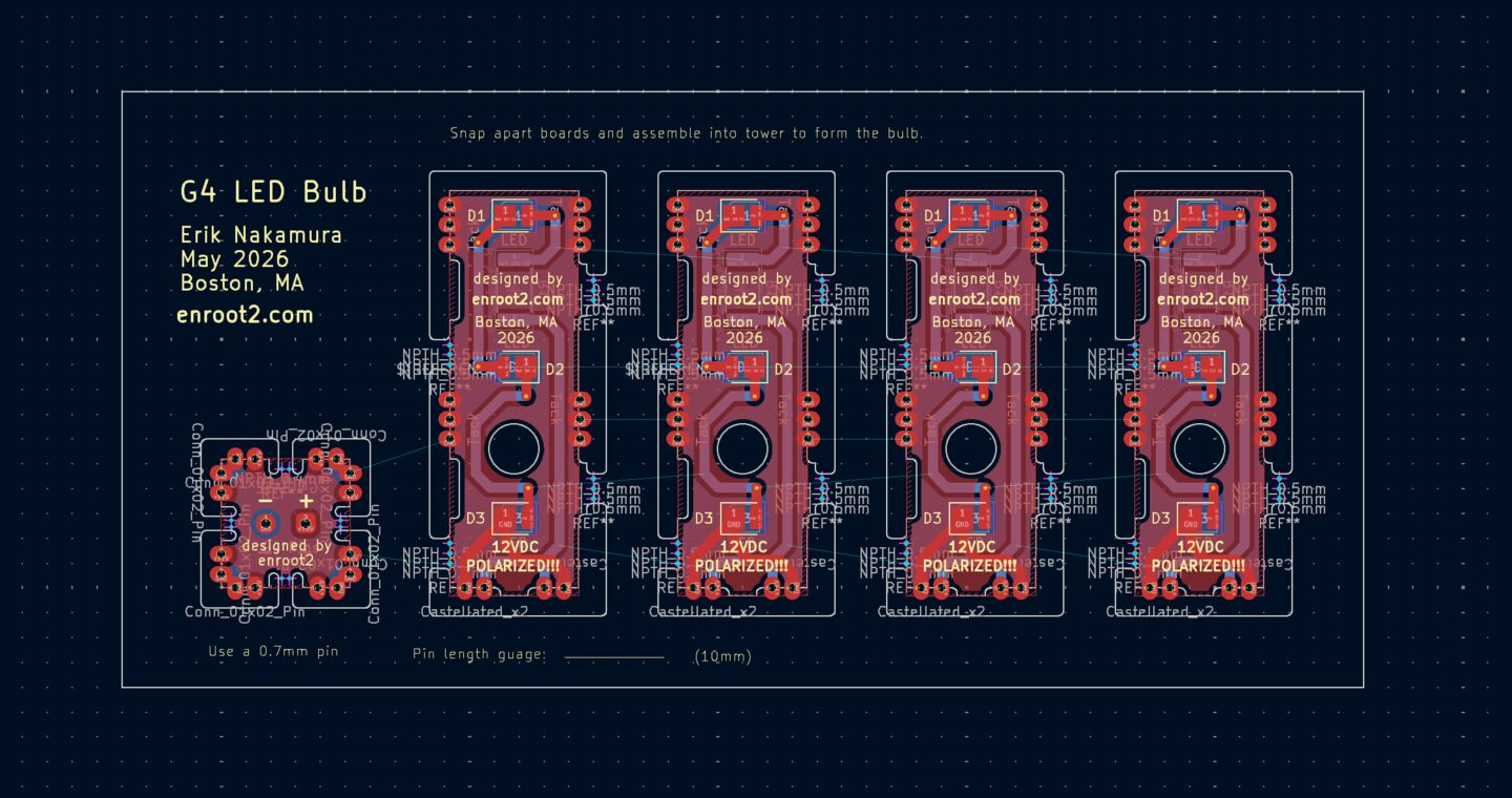
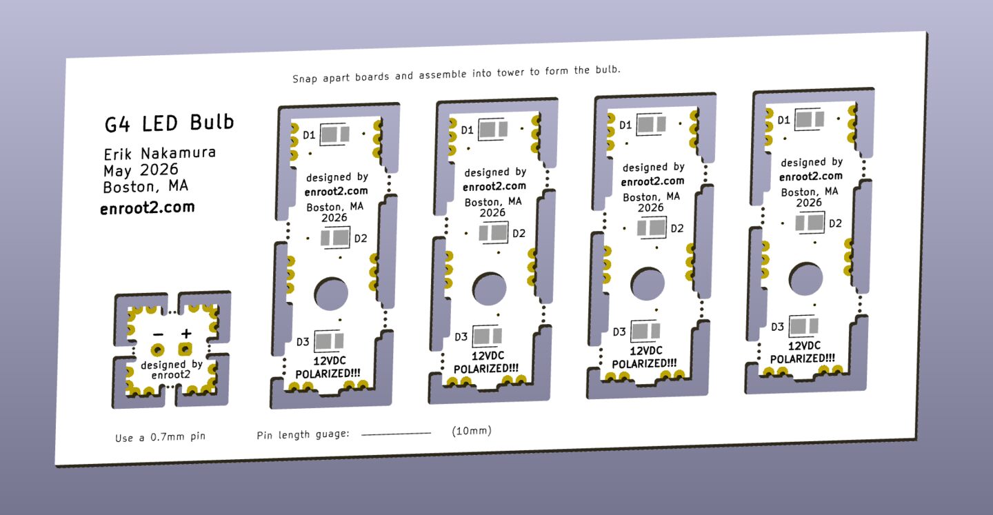
Castellation and Panalization Manufacturing Blockers
At this point, the boards were ready to fab - or so I thought. I was aware that castillated pads and panalization came with design constraints due to the special manufacturing techniques involved. I did not, however, fully understand those contraints or anticipate that combining the two techniques would result in even greater limitations.
Nor did I anticipate the significant cost associated with castillated holes.
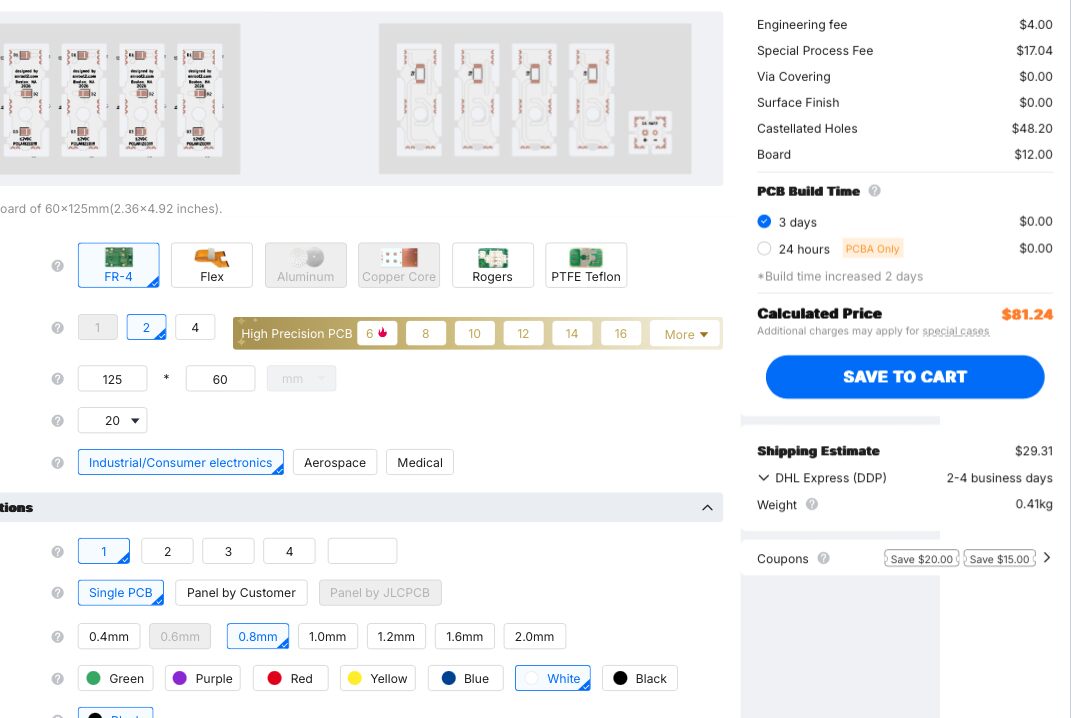
I was willing to pay the cost but the boards did not meet the clearance requirement between a castillated pad and routed corner. I resolved to design a solution that used 90 degree header pins for the mechanical and electrical connection between boards instead of castillated pads.
Connector Based Design
Back in KiCad, I created a board layout that used header pins. I needed to slightly offset each set of pins from the center to make them all fit.
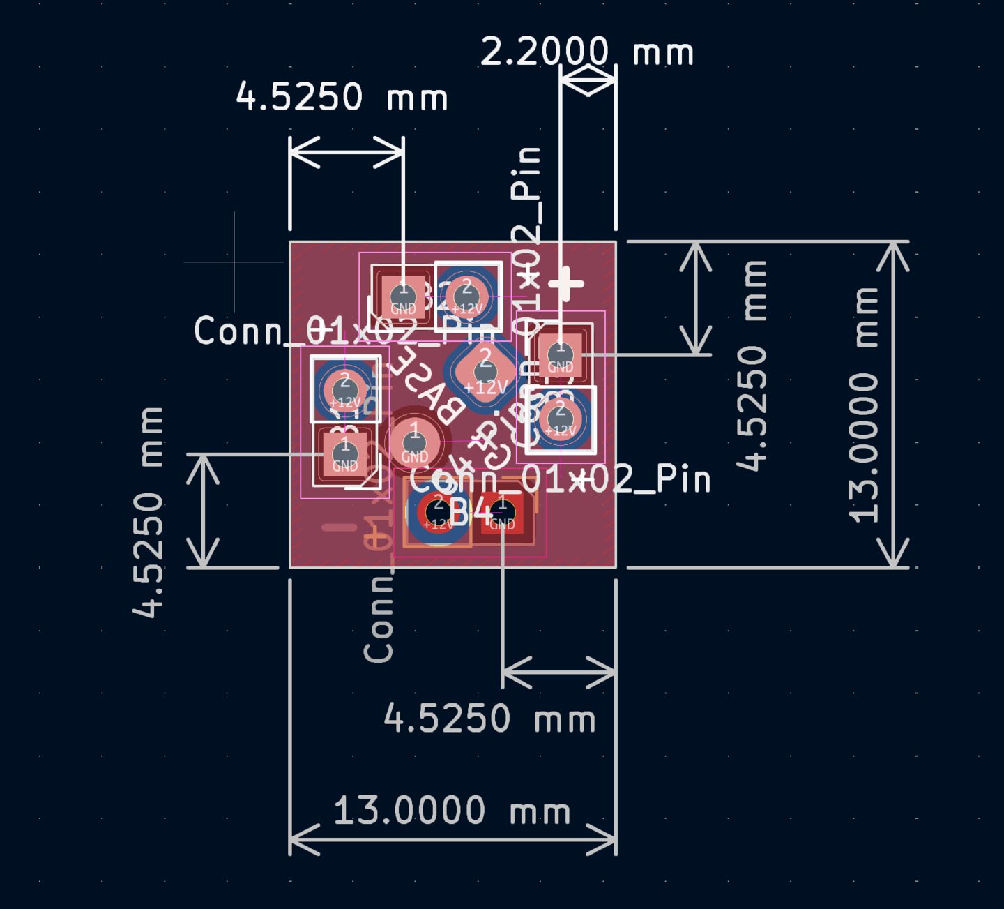
I threw the boards into Fusion to double check alignment and fit.
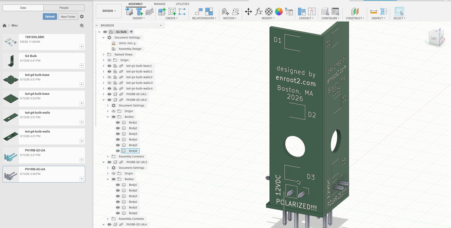
Fabrication
I used JLC PCB for the board fabrication because I've had all my PCB projects fabbed by them in the past with good results. Their prices are also extremely competative.
| Board | Quantity | Unit Price | Total Price |
|---|---|---|---|
| Walls | 100 | USD $0.50 | USD $50.21 |
| Base | 20 | USD $0.31 | USD $6.24 |
The order was shipped 7 days after I submitted it. The walls have a higher unit cost because of the white solder mask. I felt the white was important to reflect light and ensure the bulbs wouldn't be visible inside a frosted fixture.
Shipping cost was $43.93 from Shenzen to Boston, and American import taxes were $21.89, however, I also included the board for the PWM dimmer in the same order.
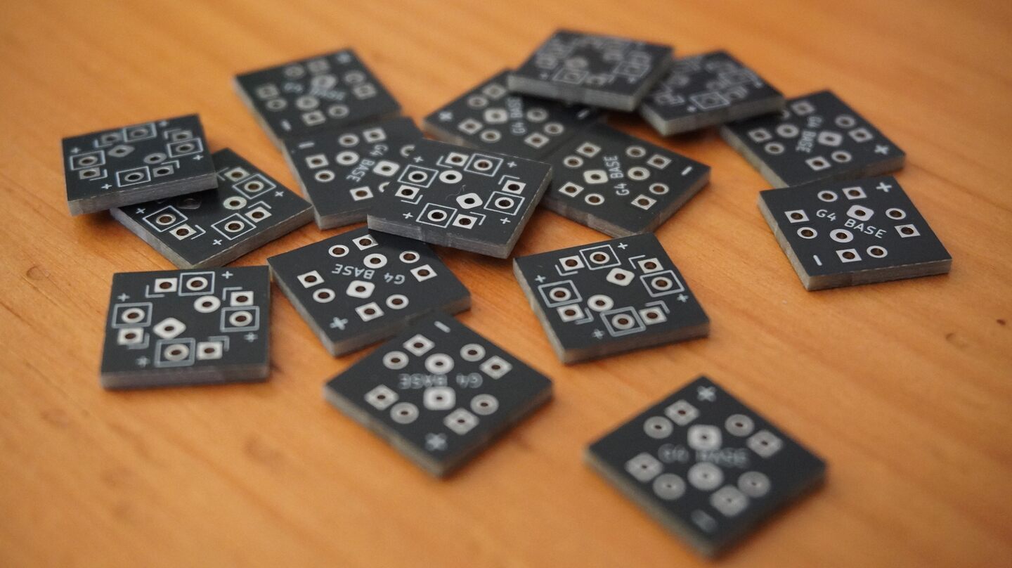
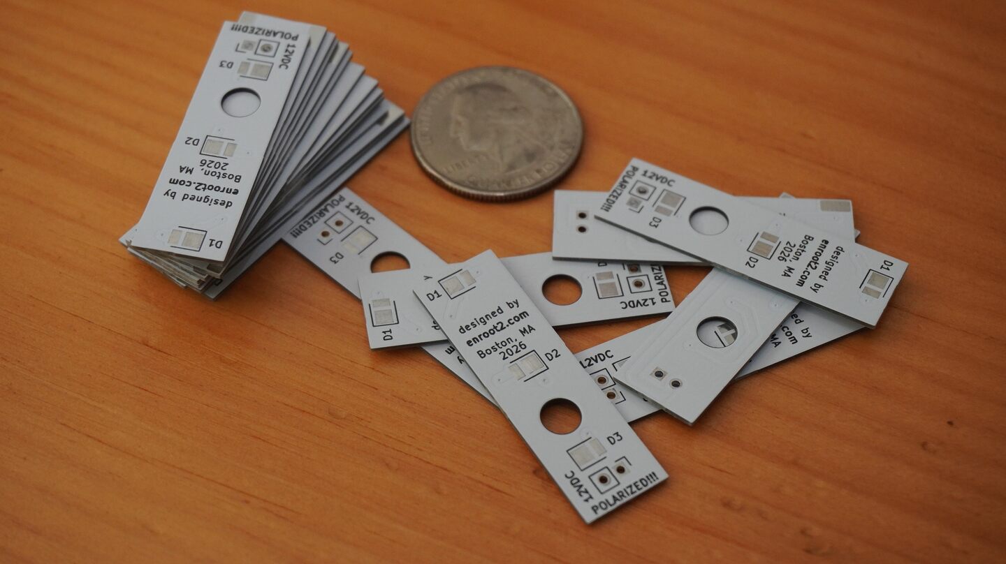
I will continue to update this post once I begin assembling the boards.
© 2024 Erik Nakamura. All rights reserved.
Use of this content is subject to the terms described in the license section of the about page.