Published on May 29, 2026
Perfect PWM Dimmer
I designed and built a 12 volt pulse width modulation (PWM) switching device to achieve a perfect dimming experience for LED lights. The circuit features high side switching to reduce EMI, controlled by an ESP32 allowing for a non-linear dimming curve calibrated to the human eye's perception of brightness. A high switching frequency of 78kHz eliminates flickering and noise. The board was fabricated oversees and assembled by myself using mostly hot air to reflow surface mount components.
What is Perfect Dimming?
Being able to control the brightness of lighting is very important for comfort. I discussed the importance of dimming in the companion article about the LED G4 lightbulbs I made.
Perfect dimming means being able to adjust brightness from 0-100% in a smooth and continuous manner. Many off-the-shelf dimmers will shoot from 0 to 10%+, or only dim in discrete steps.
Another important factor in perfect dimming is flicker. Nearly all LED dimmers work by rapidly switching the light off and on, which can lead to a perceivable flicker to either the human eye or to cameras if the on-off switching isn't fast enough. When the switching is within the audible frequency range, it can also result in a buzzing or humming noise.
Perfect dimming must smoothly cover the entire 0-100% brightness range, and be flicker free.
Waveform Lighting Comparison and Clock Speed
When researching dimmers, I cam accross Waveform Lighting's FilmGrade dimmer product and a marketing article on their blog titled Introducing FilmGrade SmoothDim technology - gradual and smooth LED dimming
The Waveform article highlights two issues with typical LED dimmers that their product solves.
First, it states that, due to pupilary response, the relationship between a light source's "light energy" and the perceived brightess is non-linear.
They go on to claim:
"One of the core features of SmoothDim technology includes a proprietary formula that produces a mapping of dimmer dial positions to light output levels that create the perception of even and gradual dimming."
(SmoothDim is a registered trademark of Waveform Lighting)
Very neat! I felt like I must have this feature in my dimmer because I want the dimming to feel smooth and linear. Although the pupilary response explanation is likely incomplete.
One method would be to purchase the dimmer from Waveform Lighting and simply measure the output in response to a known input. This would allow me to copy their mapping.
However, I figured there would already be a body of research I could use to make my own curve.
The second issue that the Waveform Lighting article highlights is large discrete steps between available brightness levels.
The article claims that their technology utilizes "more than 65,000 different brightness steps".
The "more than 65,000" number likely comes from a 16 bit dimming resolution, because
I think they must be using dithering to get that many levels of brightness.
In a simple PWM dimming sheme, the dimming range is compressed into a single pulse. The duration, i.e. width of the pulse determines the brightness. Without dithering, a very fast clock is required to chop each pulse into 65,000+ slots where we can choose how many slots to be on or off.
Even at 20kHz a 1.31GHz clock would be required to achieve 16 bits of dimming resolution. I'm assuming that the Waveform dimmer is higher than 20kHz, and a 1.31GHz clock would be pretty insane, so they are almost certainly using dithering.
In our case, the ESP32's clock is 80MHz, i.e 80 million cycles per second. At a 100kHz PWM frequency, each pulse is 10 microsecons, during which the clock will tick only 800 times. That means we can only chop each pulse into 800 slots. This is not many steps...
However, if we knock down our target PWM frequency to, say 78kHz, we now have much longer pulses and we can fit 1024 slots into one pulse. I think 1024 discrete steps should be more than enough. That's a resolution of about 0.1% which, on a 300 degree dial is 0.3 degrees, likely approaching the input accuracy of a human turning the dial.
At some point I'm planning on getting Waveform's product and tearing it down. But for now, we can use their article as inspiration.
High Side Switching
The dimmer is just a device that rapidly turns the LEDs on and off. There are two ways to turn the LEDs on and off: disconnect them from ground or disconnect them from power, i.e. low-side and high-side switching.
I knew that this dimmer would be used for a lamp with long cable runs so I went with a high-side switch. High-side switching keeps everything connected to ground, which, intuitively, felt like it would reduce electromagnetic noise.
In either case we use a MOSFET to act as the circuit-breaking component, but the kind of MOSFET if different for low and high side switching.
A low-side switch uses an N-channel MOSFET while high-side switching uses a P-channel MOSFET. Their drive circuitry is different. Here's a really great video called Everything You Need to Know About MOSFETs from the ElectrArc240 YouTube channel. They have a lot of other interesting and educational videos on the subject of electronics.
The key difference for this project is that P-channel MOSFETs are more expensive than an N-channel MOSFET with comparable capacity and efficiency. However, cost is a non-issue for this small project. Let's go!
Circuit Design
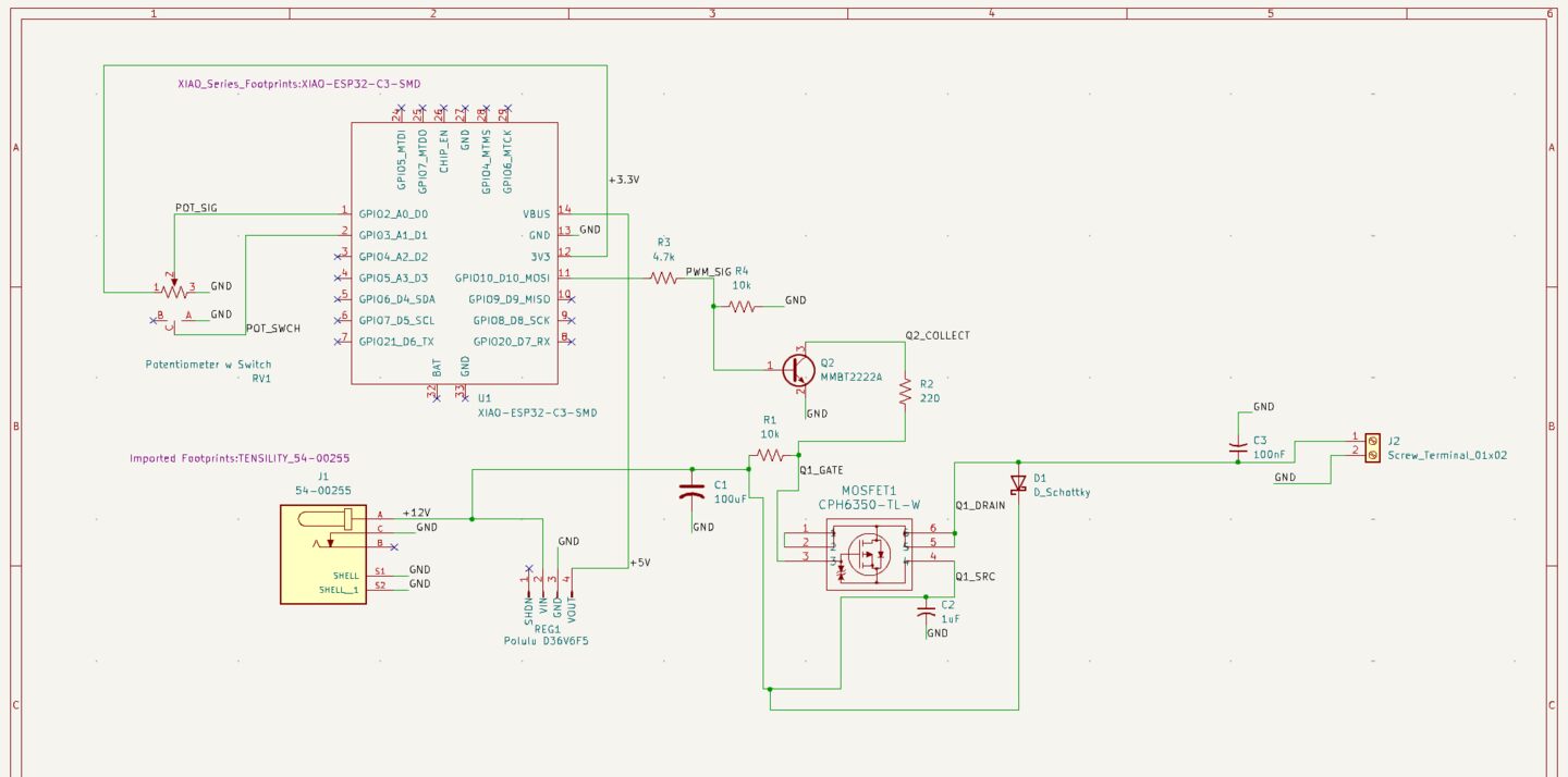
The heart of the circuit is a P-channel MOSFET driven by an NPN transistor acting as a level shifter. The ESP32's LEDC peripheral generates a PWM signal at 3.3V, which the NPN shifts into a 12V gate drive to switch the P-FET on the high side of the lamp supply. A gate resistor slows the switching edges to ~300ns to reduce EMI from the long lamp wiring. A resistor divider on the NPN base holds the FET off by default during ESP32 boot, preventing any flash at startup.
User control comes from a 10k rotary potentiometer feeding the ESP32's ADC through a simple voltage divider.
I regret the potentiometer I chose. It was really expensive (~$15), and small, making it feel dainty. Worst of all, the off position doesn't have a satifying click to it, which is something I really wanted. I ended up purchasing some cheap rotary switch pots which feel much better and I'm hoping those can act as a drop-in replacement given the simple voltage divider analog sensing.
The lamp's ground return is continuous and unswitched from input to output — only the positive rail is interrupted by the P-FET. A Pololu D36V6F5 buck module steps the 12V input down to 5V to power the ESP32. I've used the same Pololu module in the past for the wireless boiler switch project so I knew they would be a convenient solution - plus I had one left over.
Board Layout
I made the schematic and board in KiCad.
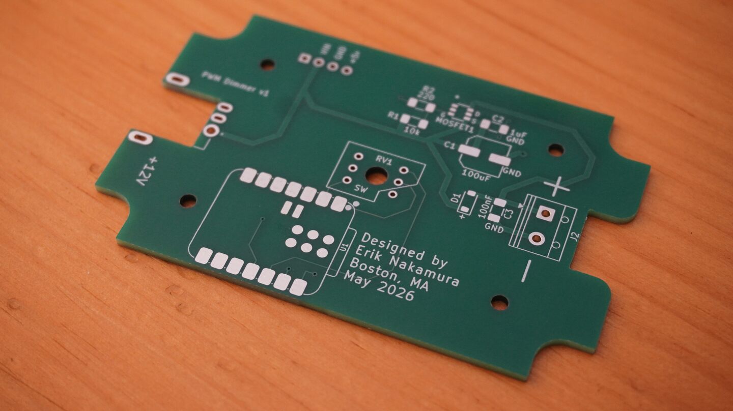
I had to lay out the board multiple times because the enclosure kept changing. The first few enclosures I chose were too small and I didn't want to squeeze the components too close together because I knew I would be hand soldering them.
Another massive constraint was my insitance on putting the dial smack in the middle of the board so the final product would look more even and symetrical.
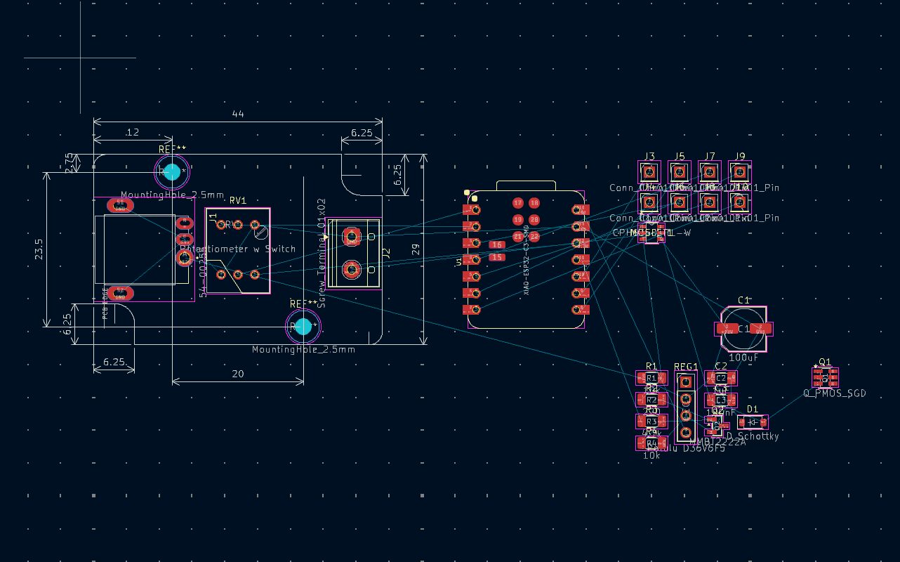
The central dial would have been fine on its own, but I also wanted to use an ESP32 as the main microcontroller to make the board more versatile. Even with the very compact Seeed Studio ESP32 XIAO module, it was difficult to fit onto the board.
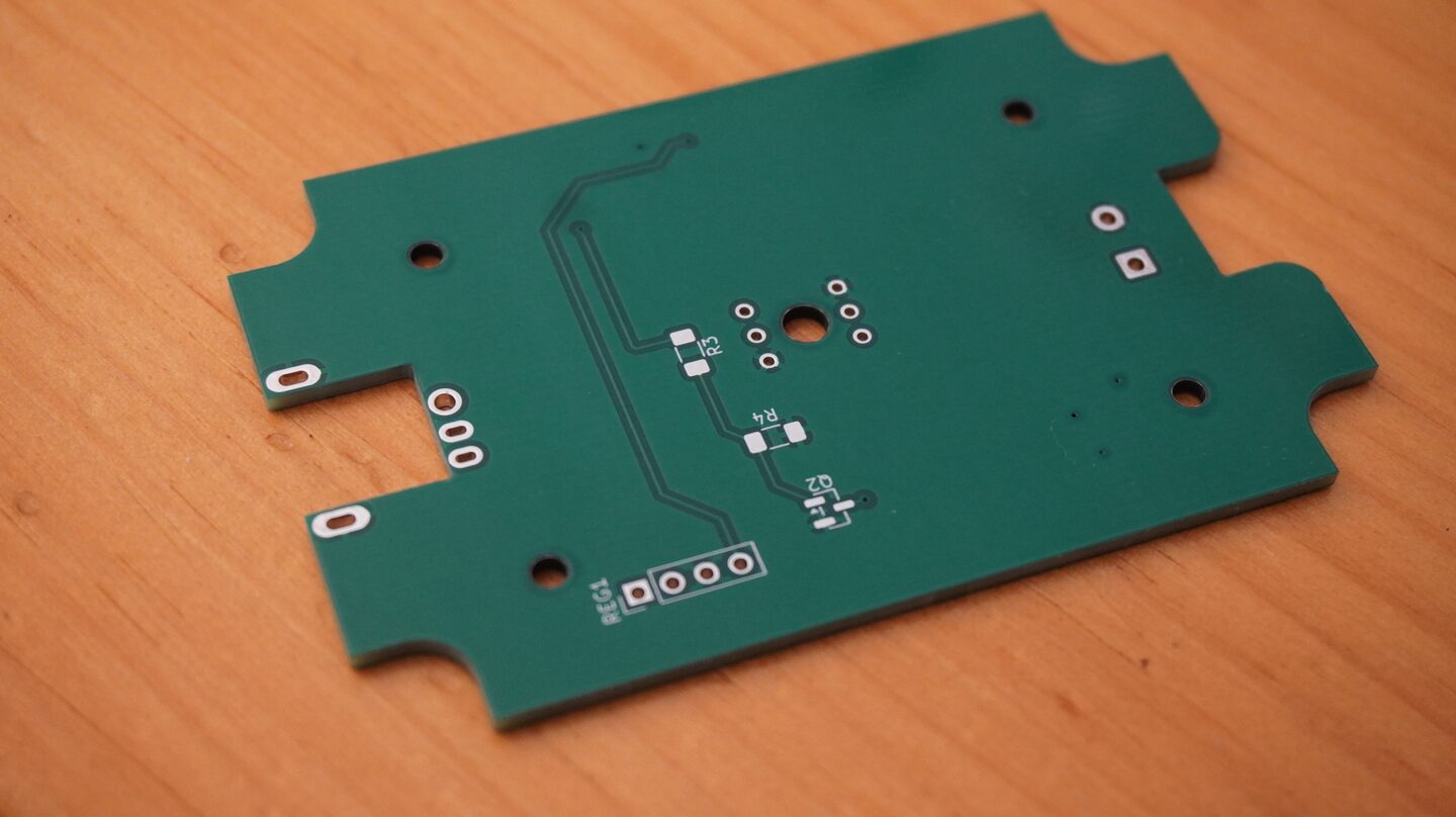
The final board dimentions were roughly 80x50mm excluding the various cutouts for the enclosure and the DC input jack. For a board of this size, the mounting screws also consume a considerable amount of space.
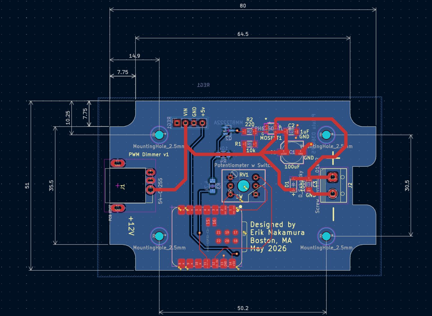
I wanted to use a board cutout mounted DC barrel jack because I thought it would land more centrally on the enclosure side wall, but we'll see how that actually works out. I also just thought it would be a neat feature to design into the board.
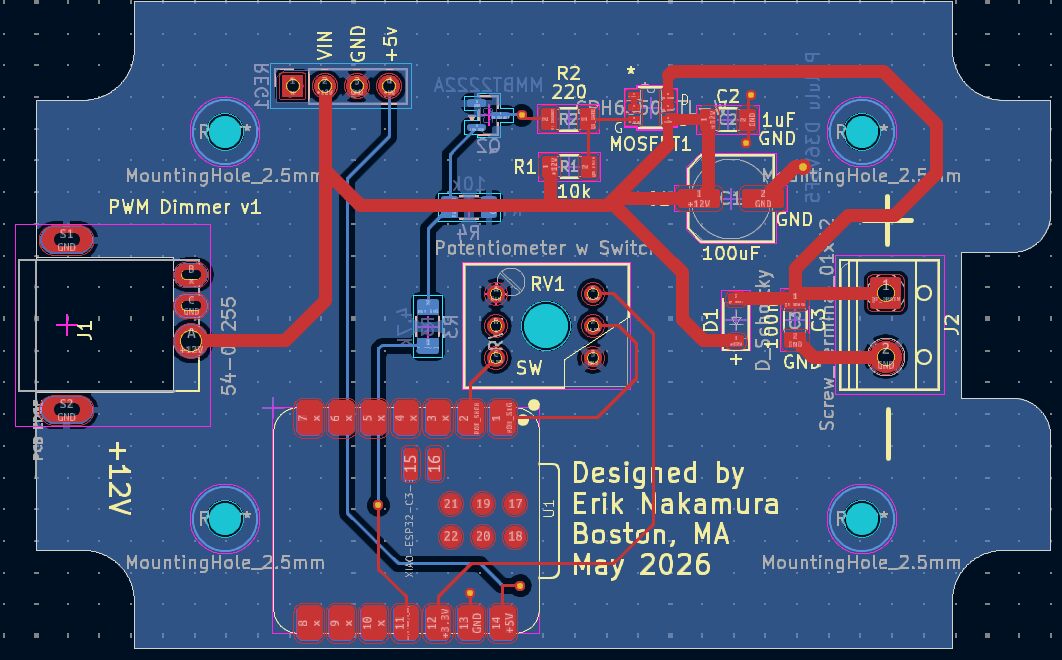
The board is two layers with one large grounded copper pour on the bottom layer. The idea behind this was to sheild the WiFi antenna from some of the noise generated by the high frequency switching in the buck converter, but I'm not really sure if it makes a real difference.
Board Fabrication
The boards were fabricated by JLC PCB in the same order as the G4 LED bulbs. You can check out that post for details about the lead time, shipping, and tarrif costs.
| Board | Quantity | Unit Price | Total Price |
|---|---|---|---|
| Dimmer | 10 | USD $0.60 | USD $6.04 |
One interesting thing about JLC pricing is that the total price is not the unit price multiplied by the quantity. It wasn't for any of the boards in the order. My interpretation of this is that their pricing calcuation is actually sub-cent, and the unit price is rounded to the nearest cent for display purposes. Very interesting!
I will continue this article when I start to assemble the boards...
© 2024 Erik Nakamura. All rights reserved.
Use of this content is subject to the terms described in the license section of the about page.