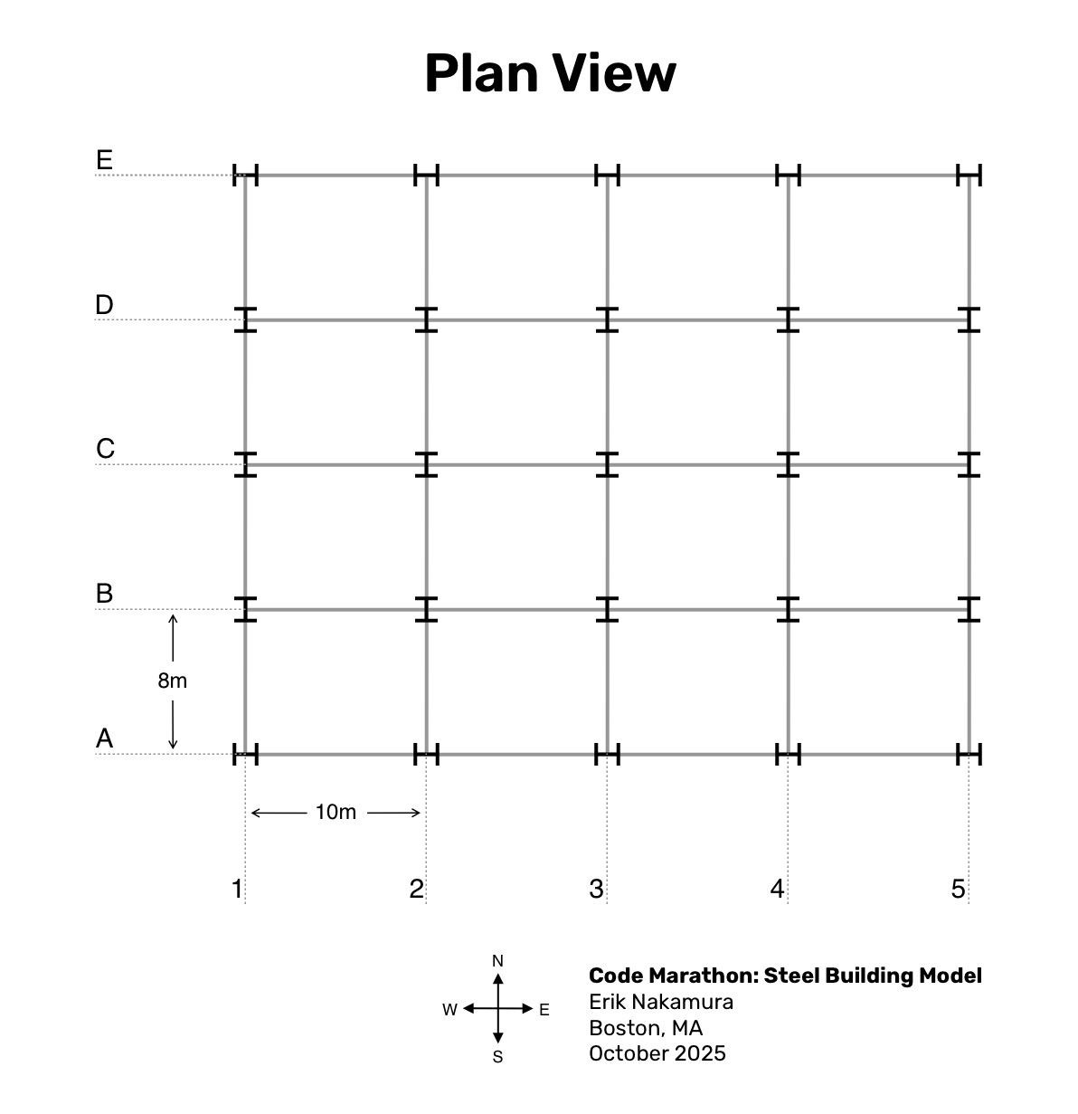
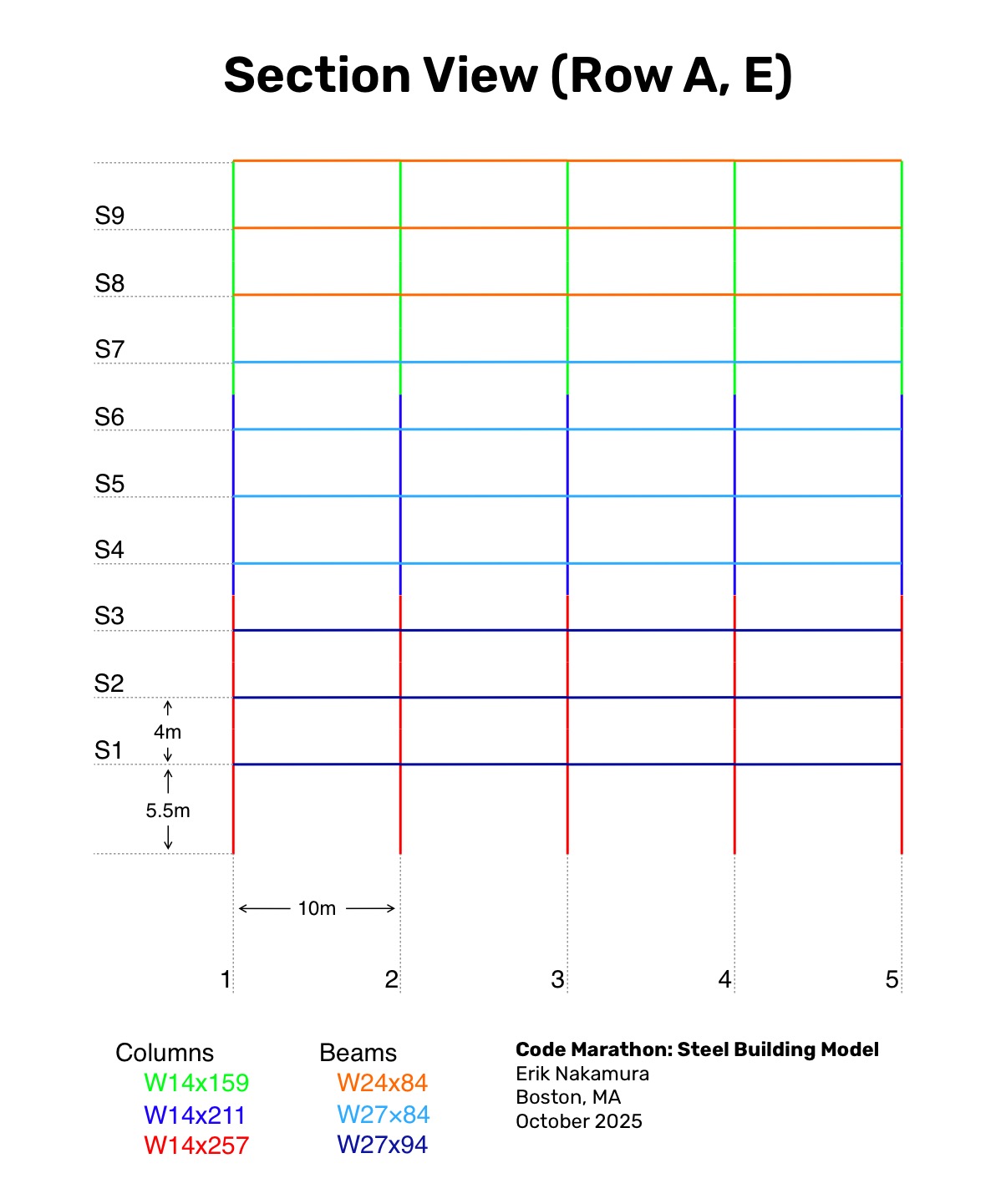
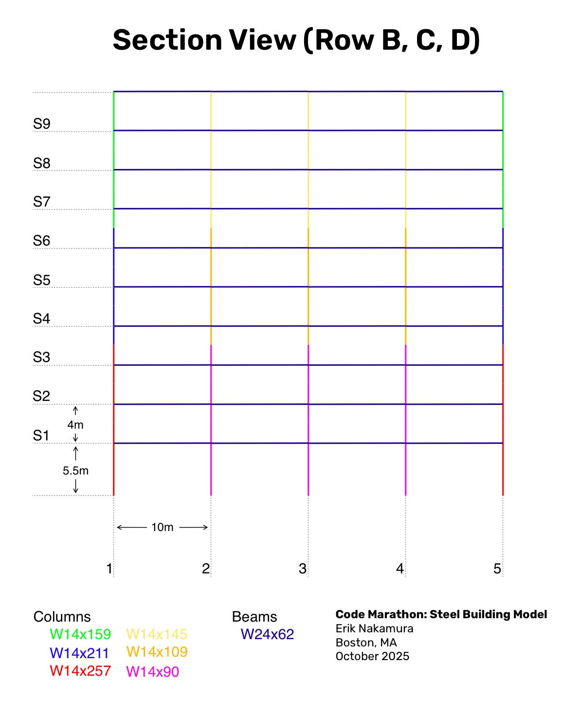
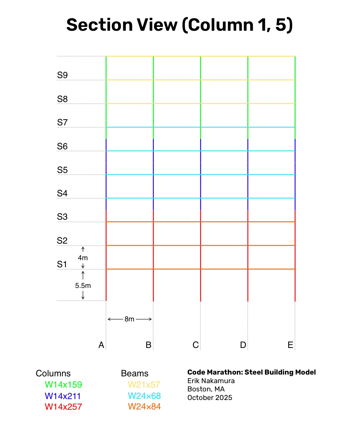
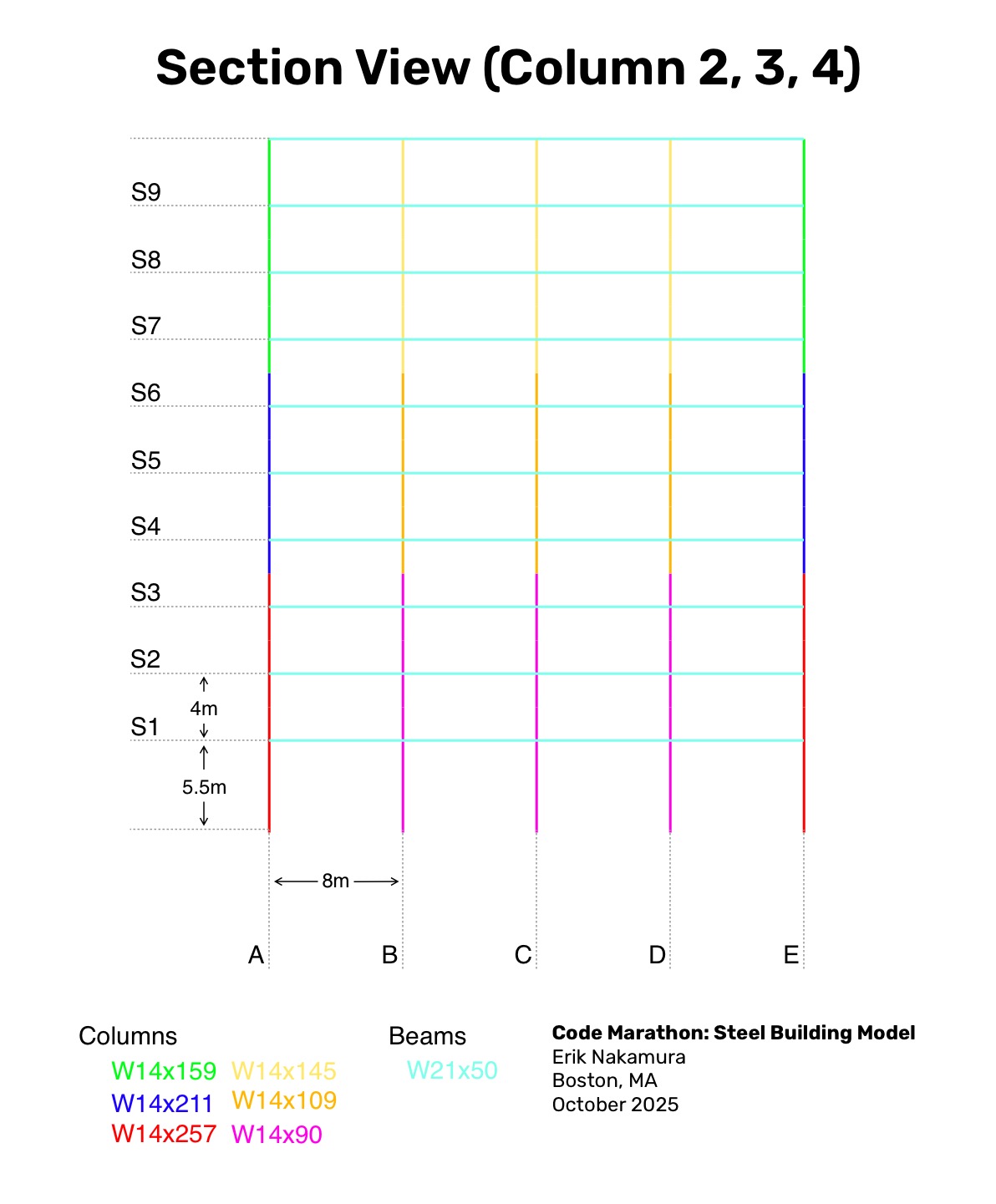
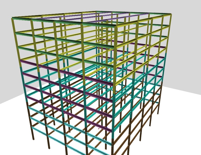
I started with a test case by defining a ten-story steel moment-frame building made up of 4x4 rectangular bays, each 10m in the east–west and 8m in the north–south direction, for an overall footprint of 40x32m. The first story is 5.5m high with upper stories at 4.0m, reaching a roof height of 41.5m. Lateral resistance is provided by moment frames along all perimeter lines: row A and E in the east–west direction and columns 1 and 5 in the north–south direction. Interior framing consists of gravity-only beams with pinned connections. Columns are continuous through all stories with splices located at the mid point between floors.
I also created a member-by-member plan where the member sizes were chosen somewhat arbitrarily based on quick research, erring on the side of undersized to make potential future analysis more interesting.
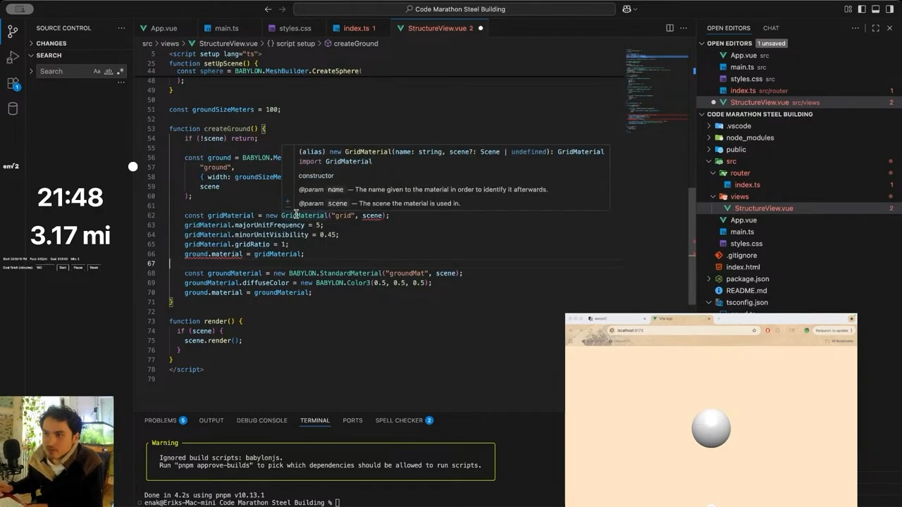
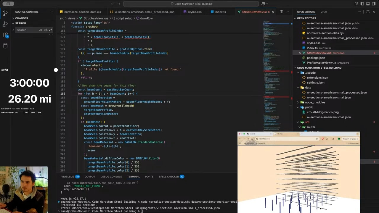
I set a goal finish of 3 hours, which is about a 7 min/mile pace. For this first code marathon I also created a little timing applet that starts a clock and counts up the miles based on the goal pace.
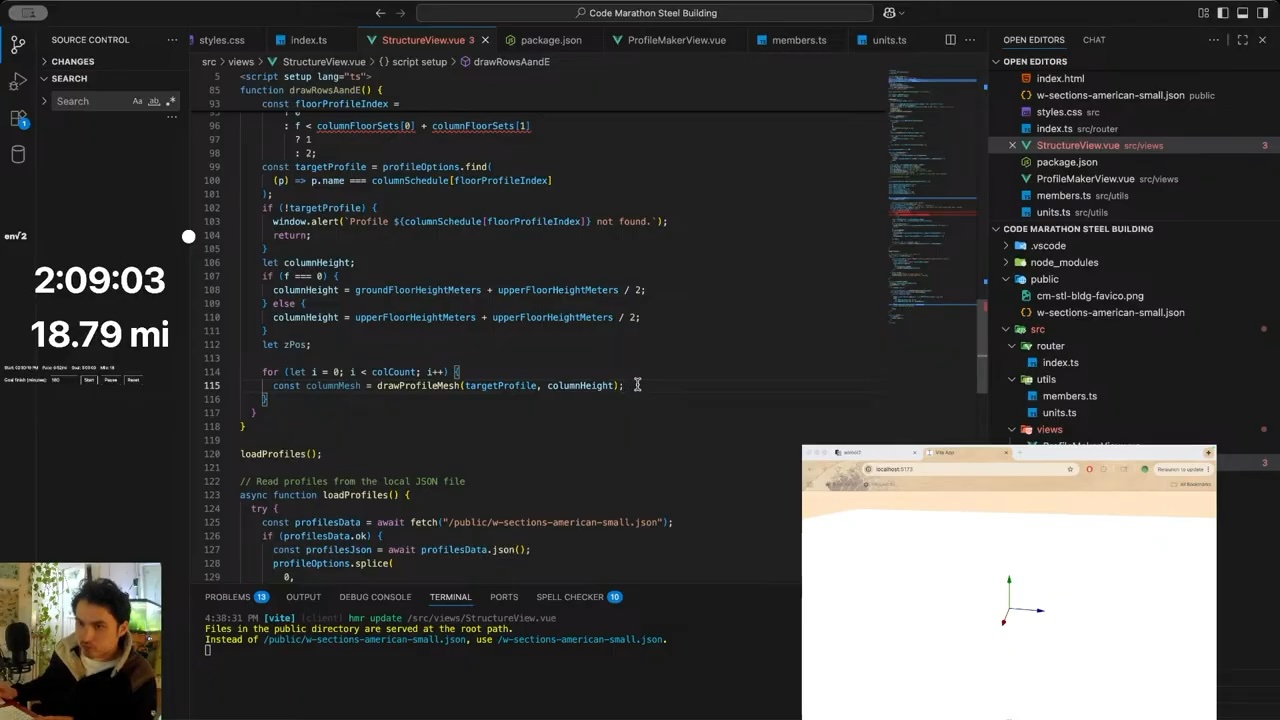
First I set up a boilerplate vue project with create vue@latest opting for a bare Typescript preset. I set up a router and some global styles for development flexibility.
I also imported Babylonjs and got a basic canvas with cameras, lights, and a floor. I tried to get a 1mx1m grid on the ground but couldn't get it working quickly enough.
This is also where I locked in the unit scale where 1 world unit is 1 meter.
I briefly pondered if I should make a wireframe model of the structure first and then replace the wires with actual steel members later, but quickly decided to skip that step given the time crunch.
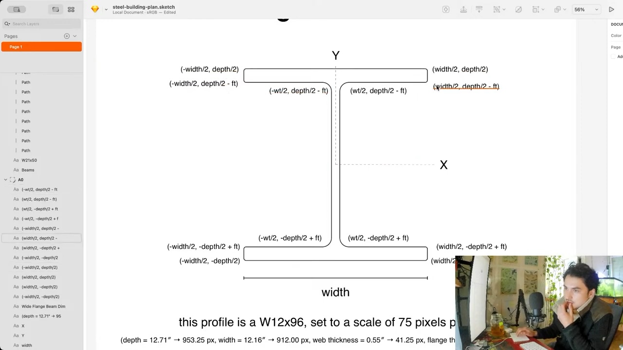
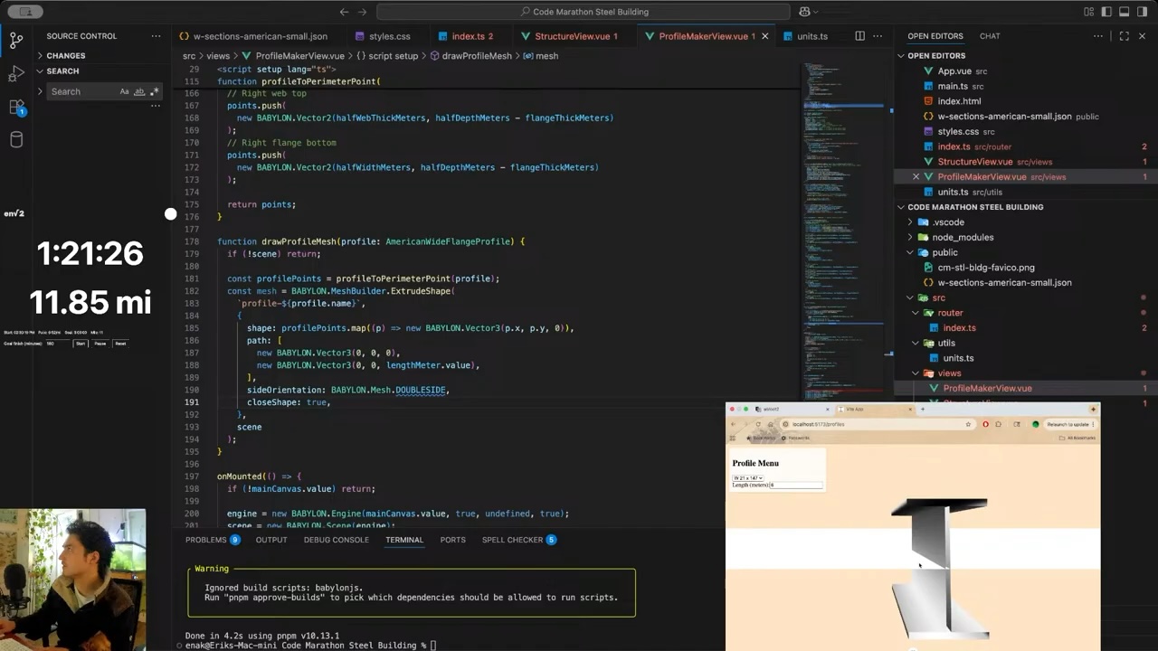
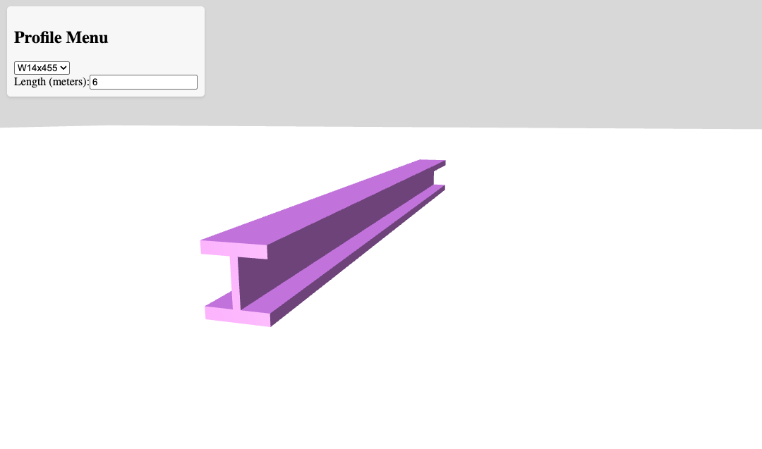
So I decided the first step should be creating the steel profiles.
Before the marathon started, I created a dataset of American (AISC) steel profiles by collecting publicly available data and forming it into a normalized JSON array. The data was poorly normalized so I used a quick JS script to clean it up and process it so that each member had the following shape:
Once I had a reliable way to create the steel members, I got started on assembling them into a building based on the plan.
First I made sure to carefully define the coordinate system. I define +x as east, +z and north, and +y as positive elevation.
I decided on a row by row approach. Each row is drawn floor by floor, and each floor is drawn west to east. This places the origin point of the building at the south west corner.
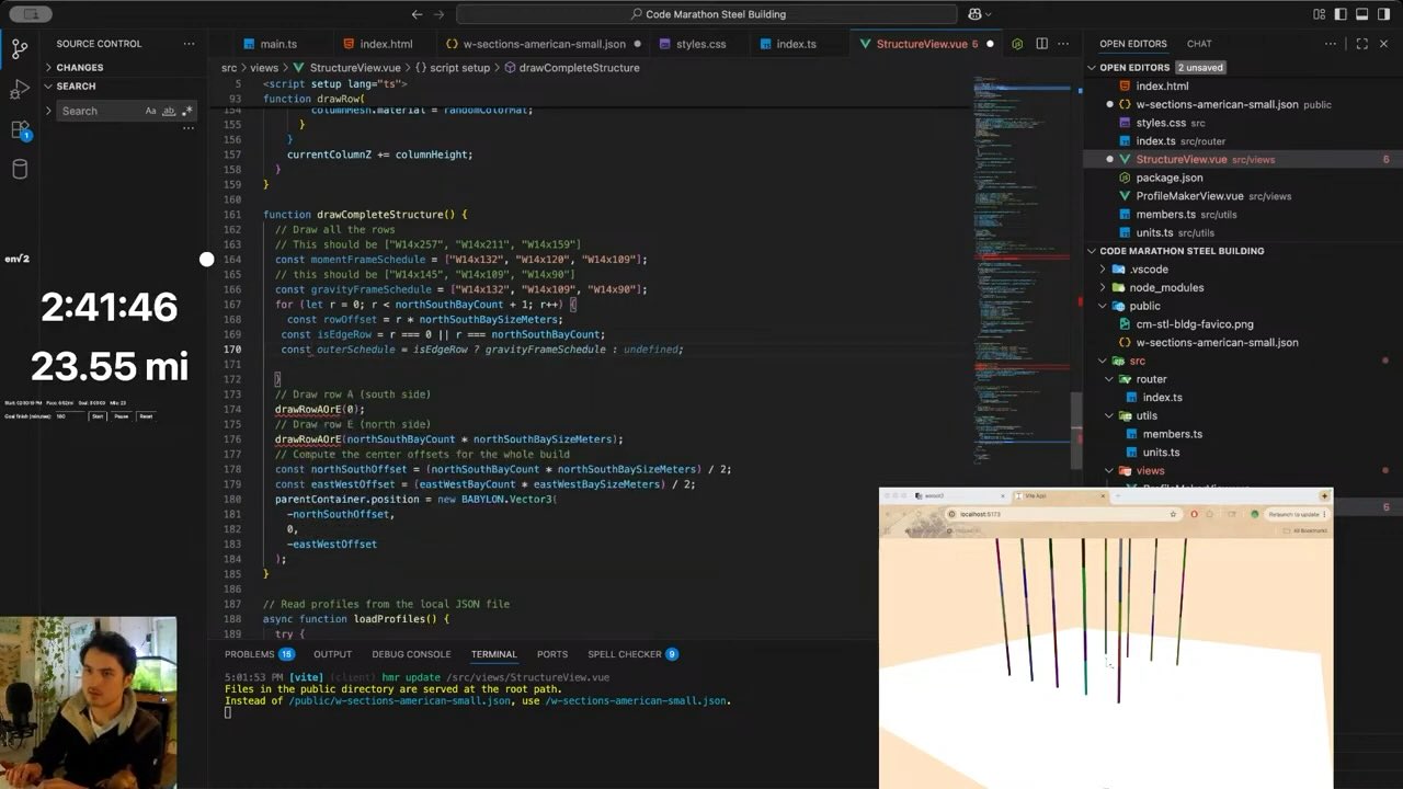
I started with all the columns.
I did the outside columns first (rows 1 and 5) to validate the row drawing function. Then did the rest.
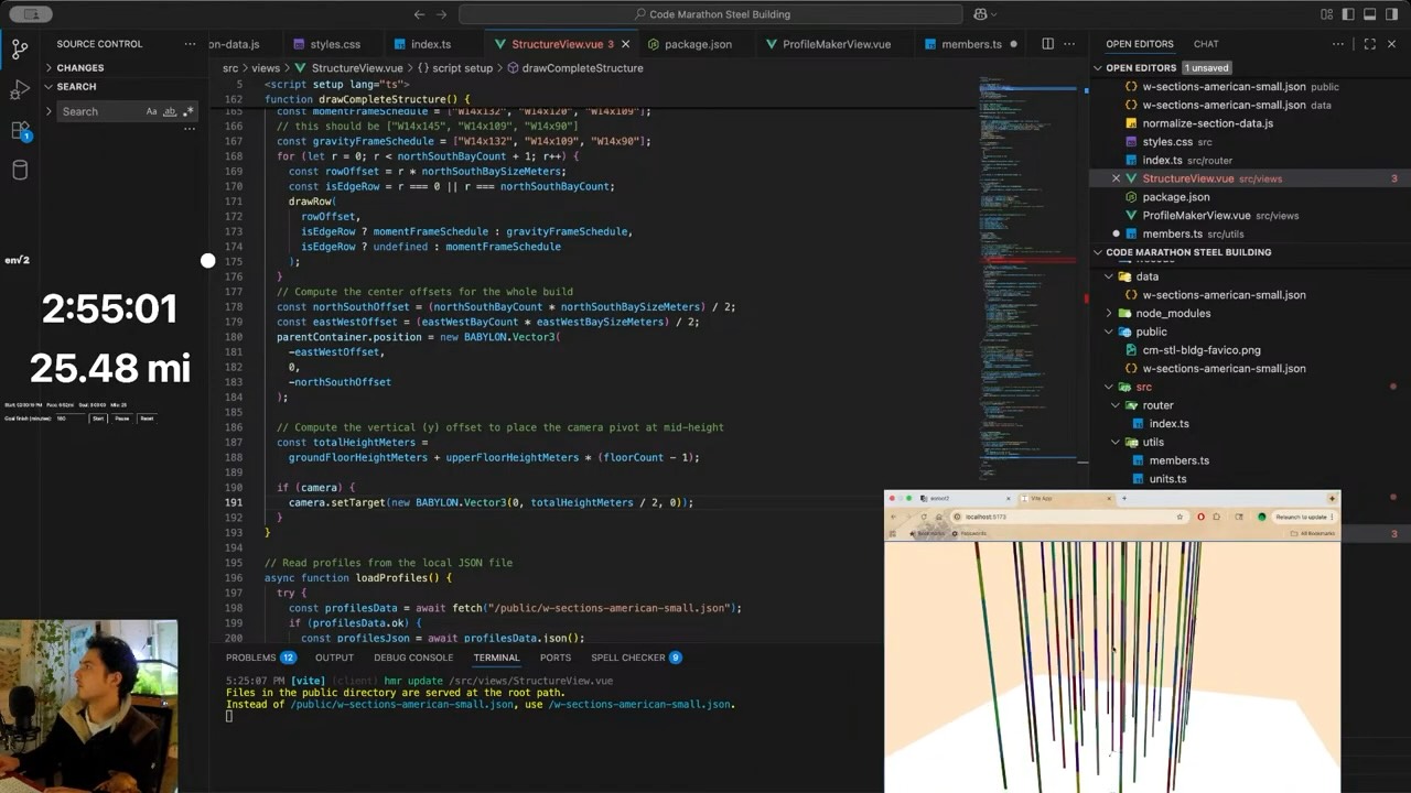
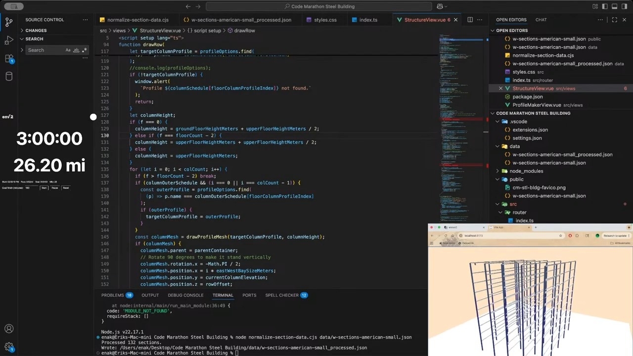
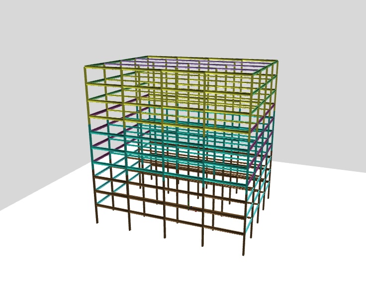
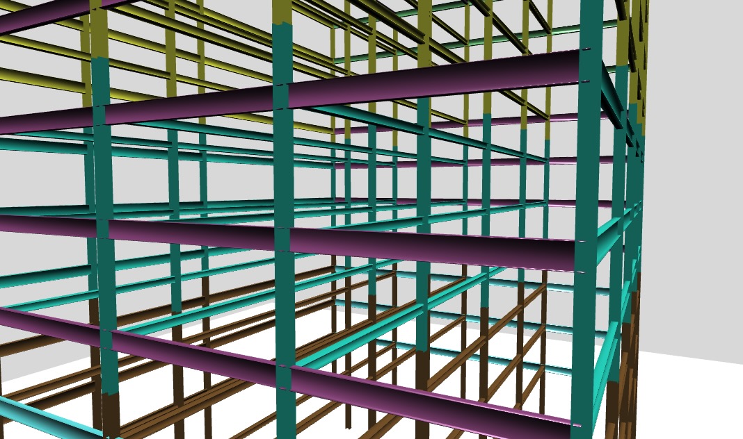
Then I did the beams. It's fun how one tiny error can throw the whole things off and create surprising and sometimes interesting results.
The only thing missing now are the beams that go between the rows.
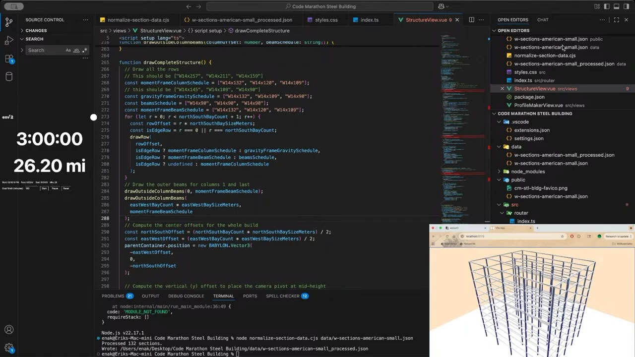
The code for the drawing functions is below. It's pretty messy but thats what makes a code marathon fun.
typescript
function drawRow( rowOffset: number, columnsSchedule: string[], beamsSchedule: string[], columnOuterSchedule?: string[]) { if (!scene) return; // Start by drawing the ground floor columns const colCount = eastWestBayCount + 1; const columnSchedule = columnsSchedule; const columnFloorSets: number[] = [3, 3, 4]; // How many floors each column type gets, stacked const beamSchedule = beamsSchedule; const beamFloorSets: number[] = [3, 4, 3]; // How many floors each beam type gets, stacked let currentColumnElevation = 0; for (let f = 0; f < floorCount; f++) { const floorColumnProfileIndex = f < columnFloorSets[0] ? 0 : f < columnFloorSets[0] + columnFloorSets[1] ? 1 : 2; let targetColumnProfile = profileOptions.find( (p) => p.name === columnSchedule[floorColumnProfileIndex] ); console.log(targetColumnProfile?.name); //console.log(profileOptions); if (!targetColumnProfile) { window.alert( `Profile ${columnSchedule[floorColumnProfileIndex]} not found.` ); return; } let columnHeight; if (f === 0) { columnHeight = groundFloorHeightMeters + upperFloorHeightMeters / 2; } else if (f === floorCount - 2) { columnHeight = upperFloorHeightMeters + upperFloorHeightMeters / 2; } else { columnHeight = upperFloorHeightMeters; } for (let i = 0; i < colCount; i++) { if (f > floorCount - 2) break; if (columnOuterSchedule && (i === 0 || i === colCount - 1)) { const outerProfile = profileOptions.find( (p) => p.name === columnOuterSchedule[floorColumnProfileIndex] ); if (outerProfile) { targetColumnProfile = outerProfile; } } const columnMesh = drawProfileMesh(targetColumnProfile, columnHeight); if (columnMesh) { columnMesh.parent = parentContainer; // Rotate 90 degrees to make it stand vertically columnMesh.rotation.x = -Math.PI / 2; columnMesh.position.x = i * eastWestBaySizeMeters; columnMesh.position.y = currentColumnElevation; columnMesh.position.z = rowOffset; // if (sharedSteelMaterial) { // columnMesh.material = sharedSteelMaterial; // } // Apply a random color material to each column for visibility const randomColorMat = new BABYLON.StandardMaterial( `mat-${f}-${i}`, scene ); let sectionColor = randomSectionColors[targetColumnProfile.name]; if (!sectionColor) { sectionColor = BABYLON.Color3.Random(); randomSectionColors[targetColumnProfile.name] = sectionColor; } randomColorMat.diffuseColor = sectionColor; columnMesh.material = randomColorMat; } } currentColumnElevation += columnHeight; const targetBeamProfileIndex = f < beamFloorSets[0] ? 0 : f < beamFloorSets[0] + beamFloorSets[1] ? 1 : 2; const targetBeamProfile = profileOptions.find( (p) => p.name === beamSchedule[targetBeamProfileIndex] ); if (!targetBeamProfile) { window.alert( `Profile ${beamSchedule[targetBeamProfileIndex]} not found.` ); return; } // Now draw the beams for this floor const beamCount = eastWestBayCount; for (let b = 0; b < beamCount; b++) { const beamElevation = groundFloorHeightMeters + upperFloorHeightMeters * f; const beamMesh = drawProfileMesh( targetBeamProfile, eastWestBaySizeMeters ); if (beamMesh) { beamMesh.rotation.y = Math.PI / 2; beamMesh.parent = parentContainer; beamMesh.position.x = b * eastWestBaySizeMeters; beamMesh.position.y = beamElevation; beamMesh.position.z = rowOffset; const beamMaterial = new BABYLON.StandardMaterial( `beam-mat-${f}-${b}`, scene ); let sectionColor = randomSectionColors[targetColumnProfile.name]; if (!sectionColor) { sectionColor = BABYLON.Color3.Random(); randomSectionColors[targetColumnProfile.name] = sectionColor; } beamMaterial.diffuseColor = sectionColor; beamMesh.material = beamMaterial; } } }}function drawOutsideColumnBeams(columnOffset: number, beamSchedule: string[]) { // Draw the outer beams for columns 1 and last const beamFloorSets: number[] = [3, 4, 3]; // How many floors each beam type gets, stacked let currentBeamElevation = 0; for (let f = 0; f < floorCount; f++) { const targetBeamProfileIndex = f < beamFloorSets[0] ? 0 : f < beamFloorSets[0] + beamFloorSets[1] ? 1 : 2; const targetBeamProfile = profileOptions.find( (p) => p.name === beamSchedule[targetBeamProfileIndex] ); if (!targetBeamProfile) { window.alert( `Profile ${beamSchedule[targetBeamProfileIndex]} not found.` ); return; } // Now draw the beams for this floor const beamCount = northSouthBayCount; for (let b = 0; b < beamCount; b++) { const beamElevation = groundFloorHeightMeters + upperFloorHeightMeters * f; const beamMesh = drawProfileMesh( targetBeamProfile, northSouthBaySizeMeters ); if (beamMesh) { //beamMesh.rotation.y = Math.PI / 2; beamMesh.parent = parentContainer; beamMesh.position.x = columnOffset; beamMesh.position.y = beamElevation; beamMesh.position.z = b * northSouthBaySizeMeters; const beamMaterial = new BABYLON.StandardMaterial( `beam-mat-${f}-${b}`, scene ); let sectionColor = randomSectionColors[targetBeamProfile.name]; if (!sectionColor) { sectionColor = BABYLON.Color3.Random(); randomSectionColors[targetBeamProfile.name] = sectionColor; } beamMaterial.diffuseColor = sectionColor; beamMesh.material = beamMaterial; } } }}function drawCompleteStructure() { // Draw all the rows const momentFrameColumnSchedule = ["W14x257", "W14x211", "W14x159"]; const gravityFrameGravitySchedule = ["W14x132", "W14x109", "W14x90"]; const beamsSchedule = ["W14x90", "W14x90", "W14x90"]; const momentFrameBeamSchedule = ["W27x94", "W27x84", "W24x84"]; for (let r = 0; r < northSouthBayCount + 1; r++) { const rowOffset = r * northSouthBaySizeMeters; const isEdgeRow = r === 0 || r === northSouthBayCount; drawRow( rowOffset, isEdgeRow ? momentFrameColumnSchedule : gravityFrameGravitySchedule, isEdgeRow ? momentFrameBeamSchedule : beamsSchedule, isEdgeRow ? undefined : momentFrameColumnSchedule ); } // Draw the outer beams for columns 1 and last drawOutsideColumnBeams(0, momentFrameBeamSchedule); drawOutsideColumnBeams( eastWestBayCount * eastWestBaySizeMeters, momentFrameBeamSchedule ); // Compute the center offsets for the whole build const northSouthOffset = (northSouthBayCount * northSouthBaySizeMeters) / 2; const eastWestOffset = (eastWestBayCount * eastWestBaySizeMeters) / 2; parentContainer.position = new BABYLON.Vector3( -eastWestOffset, 0, -northSouthOffset ); // Compute the vertical (y) offset to place the camera pivot at mid-height const totalHeightMeters = groundFloorHeightMeters + upperFloorHeightMeters * (floorCount - 1); if (camera) { camera.setTarget(new BABYLON.Vector3(0, totalHeightMeters / 2, 0)); }}
I had a lot of fun with this challenge although the stream itself was a fail. There was no audio for a significant portion due to an OBS misconfiguration, and my webcam also dropped out.
I'll probably spin off the steel member generator as an applet on this site, and definitely upload the JSON steel profile data somewhere on this site too.
For the next stream, I want to do a truss bridge and run analysis on it. But who knows? I might come back to play with this building some more.
A. Kaveh, M. Fahimi Farzam, and M. Kalateh Ahani, “Optimum design of steel frame structures considering construction cost and seismic damage,” Smart Structures and Systems, vol. 16, no. 1, pp. 1–26, Jul. 2015, doi: 10.12989/sss.2015.16.1.001.www.researchgate.net